Radar device and radar detection method

a detection method and radar technology, applied in the direction of antennas, instruments, antenna details, etc., can solve the problems of significant abnormal antenna shape or beam pattern, etc., and achieve the effect of preventing the deterioration of target sensing performan

Active Publication Date: 2020-07-21
HL KLEMOVE CORP
View PDF15 Cites 0 Cited by
  • Summary
  • Abstract
  • Description
  • Claims
  • Application Information

AI Technical Summary

Benefits of technology

[0010]Further, another object of the embodiments is provide a radar device having a structure that reduces the influence of an internal reflected wave, which is capable of preventing a target sensing performance from being deteriorated by a reflected wave reflected within the radar device, while having a cover structure that is capable of protecting an antenna from the outside.
[0038]According to the above-described embodiments, it is possible to provide a laser device having a cover structure that is capable of protecting an antenna from the outside.
[0039]According to the embodiments it is possible to provide a radar device having a structure of reducing the influence of an internal reflected wave, which is capable of preventing a target sensing performance from being deteriorated by a reflected wave reflected within the radar device, while having a cover structure that is capable of protecting an antenna from the outside.

Problems solved by technology

However, when an antenna (a transmission antenna or a reception antenna) included in the radar device is flawed or contaminated with dust or dirt, an abnormal antenna shape or beam pattern may be caused.
As a result, a normal transmission signal is not radiated from the radar device, or a reflected wave, which is reflected from the target, of the radiated transmission signal does not reach the reception antenna normally, so that target sensing performance may be significantly deteriorated.

Method used


Image

  • Radar device and radar detection method
  • Radar device and radar detection method
  • Radar device and radar detection method

Examples


first embodiment

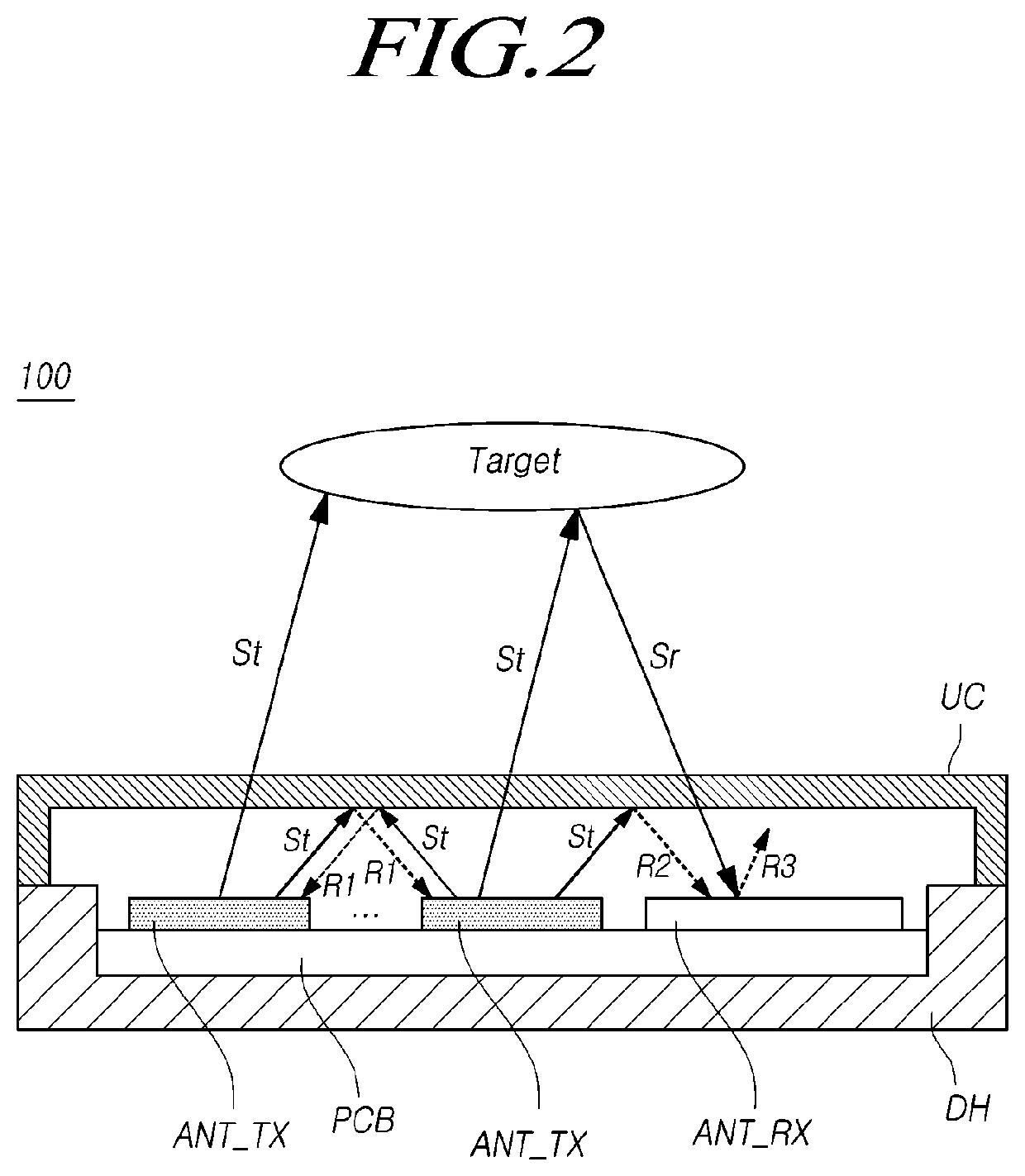
[0064]FIG. 2 is a view illustrating a radar device 100 according to a

[0065]Referring to FIG. 2, the radar device 100 according to the first embodiment includes at least one transmission antenna ANT_TX, at least one reception antenna ANT_RX, a lower housing DH and an upper cover UC that accommodate the transmission antenna ANT_TX and the reception antenna ANT_RX, and the like.

[0066]The transmission antenna ANT_TX and the reception antenna ANT_RX may be mounted on a printed circuit board (PCB) that is accommodated in the lower housing DH.

[0067]The upper cover UC is capable of preventing the transmission antenna ANT_TX and the reception antenna ANT_RX from being damaged, or preventing dirt, dust, or the like from being attached to the transmission antenna ANT_TX and the reception antenna ANT_RX.

[0068]Accordingly, the upper cover UC is capable of preventing the antenna from taking on an abnormal shape or generating an abnormal beam pattern, thereby maintaining antenna performance. Such ...

second embodiment

[0102]FIG. 5 is a view illustrating a radar device 100 according to a

[0103]Referring to FIG. 5, the radar device 100 according to the second embodiment may include at least one transmission antenna ANT_TX and at least one reception antenna ANT_RX.

[0104]As in FIG. 2, the radar device 100 according to the second embodiment may include a lower housing DH and an upper cover UC that accommodate the reception antenna ANT_RX.

[0105]The at least one transmission antenna ANT_TX may output a transmission polarization signal St having a predetermined transmission polarization angle θt.

[0106]While FIG. 5 illustrates that the radar device 100 includes only one transmission antenna ANT_TX for the convenience of explanation, the radar device 100 may include two or more transmission antennas ANT_TX.

[0107]Meanwhile, when the radar device 100 includes two or more transmission antennas ANT_TX, the two or more respective transmission antennas ANT_TX may have the same or different sensing ranges defined ...

third embodiment

[0193]FIG. 12 illustrates a radar device 100 having the stacked structure as described above.

[0194]FIG. 12 is a view illustrating a radar device 100 according to a third embodiment.

[0195]Referring to FIG. 12, in the radar device 100 according to the third embodiment, a first dielectric layer 510, in which the first transmission-side dielectric 510t and the first reception-side dielectric 510r of FIG. 5 are integrated, may be positioned on a transmission antenna ANT_TX and a reception antenna ANT_RX.

[0196]On the first dielectric layer 510, a first transmission-side strip conductor 520t and a first reception-side strip conductor 520r may be positioned in a transmission antenna region and a reception antenna region, respectively.

[0197]A ferromagnetic layer 530, in which the transmission-side ferromagnetic material 530t and the reception-side ferromagnetic material 530r of FIG. 5 are integrated, may be positioned on the region in which the first transmission-side strip conductor 520t a...


PUM


Abstract

Embodiments disclosed herein relates to a radar device, and more particularly, to a radar device having a structure that reduces the influence of an internal reflected wave, which is capable of preventing a target sensing performance from being deteriorated by a reflected wave reflected within the radar device, while having a cover structure that is capable of protecting an antenna from the outside.

Description

CROSS REFERENCE TO RELATED APPLICATION[0001]This application claims priority from Korean Patent Application No. 10-2016-0047841, filed on Apr. 19, 2016, which is hereby incorporated by reference for all purposes as if fully set forth herein.BACKGROUND OF THE INVENTION1. Field of the invention[0002]Embodiments disclosed herein relate to a radar device and a radar detection method.2. Description of the Prior Art[0003]A radar device is a sensor for detecting a target therearound, and is widely used in various fields, including civilian and military fields.[0004]Such a radar device is mounted on a vehicle, an aircraft, and the like, and is being used by being fused with various application technologies.[0005]For example, when a radar device is equipped in a vehicle, the radar device senses a peripheral obstacle, such as a vehicle or a pedestrian in front of the vehicle equipped with the radar device, and a control system of the vehicle equipped with the radar device may perform control ...

Claims


Application Information

Patent Timeline
Patent Type & Authority Patents(United States)
IPC IPC(8): G01S13/04G01S13/931H01Q17/00
CPCG01S13/04G01S13/931H01Q17/00G01S2013/9325G01S7/02G01S7/027H01Q1/425H01Q1/3233G01S7/025H01Q15/22G01S7/038G01S2013/93271G01S7/4004G01S7/4039
Inventor CHO, HYEON DONG
Owner HL KLEMOVE CORP
Why Eureka
Try Eureka