Permanent magnet motor with specific magnets and magnetic circuit arrangement

Inactive Publication Date: 2000-01-11
OKUMA CORP
View PDF10 Cites 22 Cited by
  • Summary
  • Abstract
  • Description
  • Claims
  • Application Information

AI Technical Summary

Problems solved by technology

However, the effects of limitations of driving frequency and leaked inductance of a motor, in general, make high-speed rotation difficult because the driving frequency for controllable drive increases by approximately eight times.
The motor shown in FIG. 11 has a problem in that effective use has not been made of the magnetic flux of respective permanent magnets.
Accordingly, it is impossible to make full use of magnetic flux of the north pole on the protruding pole of the stator located between the slot S4 and S5, and the same on the other respective protruding poles of the stator, which in turn causes insufficient effective magnetic flux to be obtained.
As a result, this produces a problem that the motor torque decreases.
The portion of B2 closes magnetic flux between adjoin

Method used


Image

  • Permanent magnet motor with specific magnets and magnetic circuit arrangement
  • Permanent magnet motor with specific magnets and magnetic circuit arrangement
  • Permanent magnet motor with specific magnets and magnetic circuit arrangement

Examples


Embodiment Construction

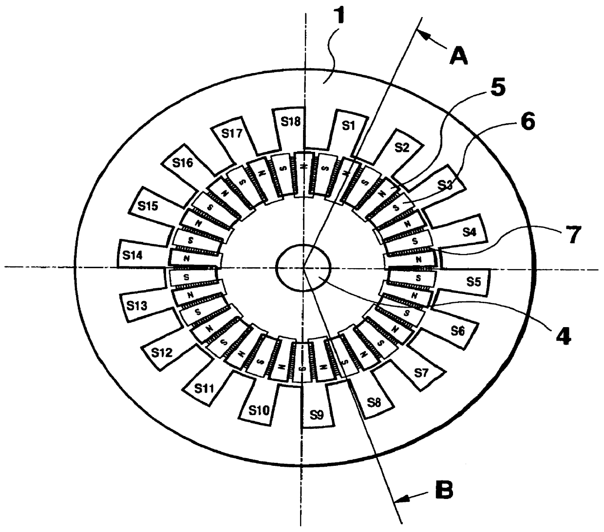
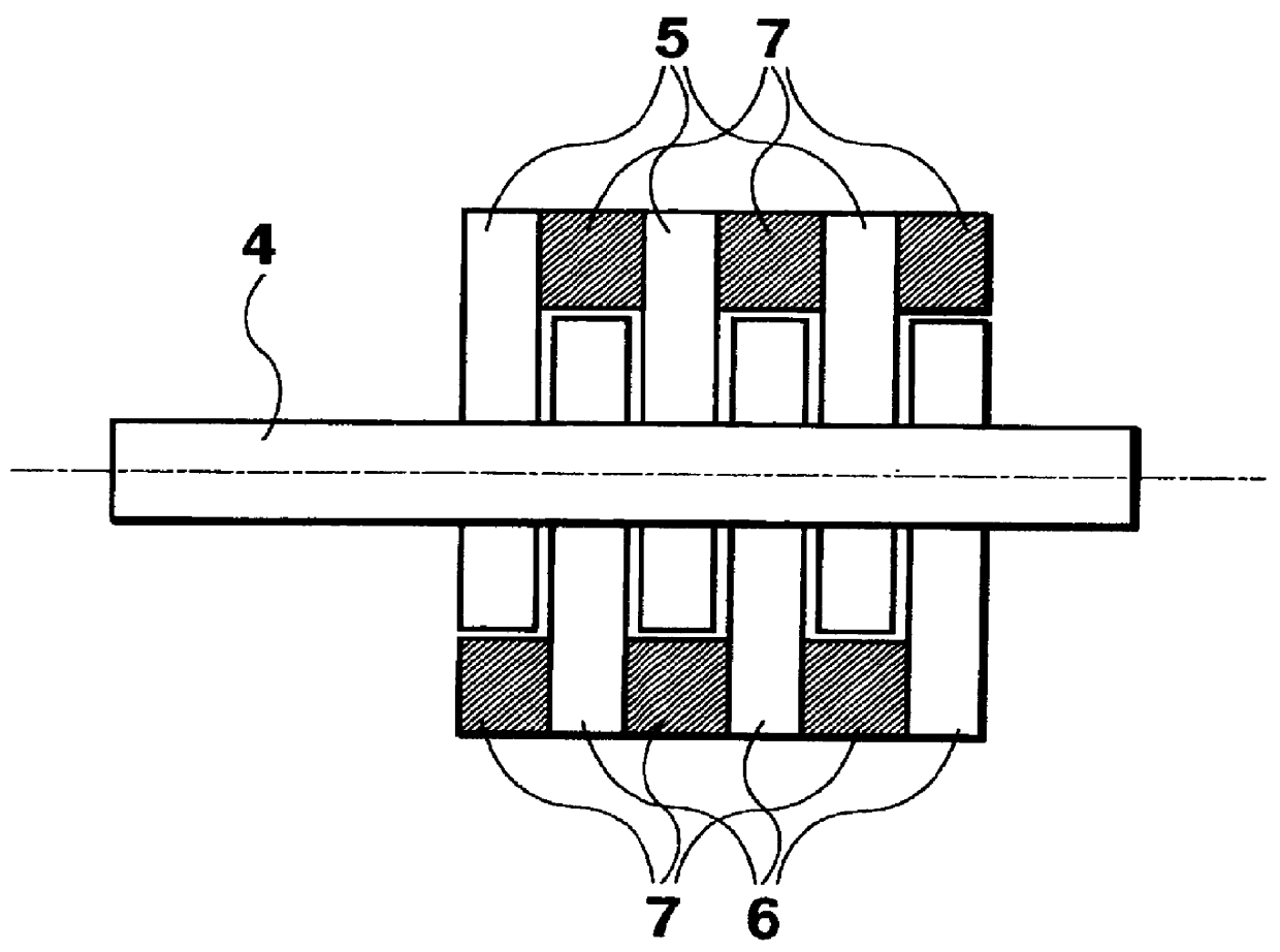
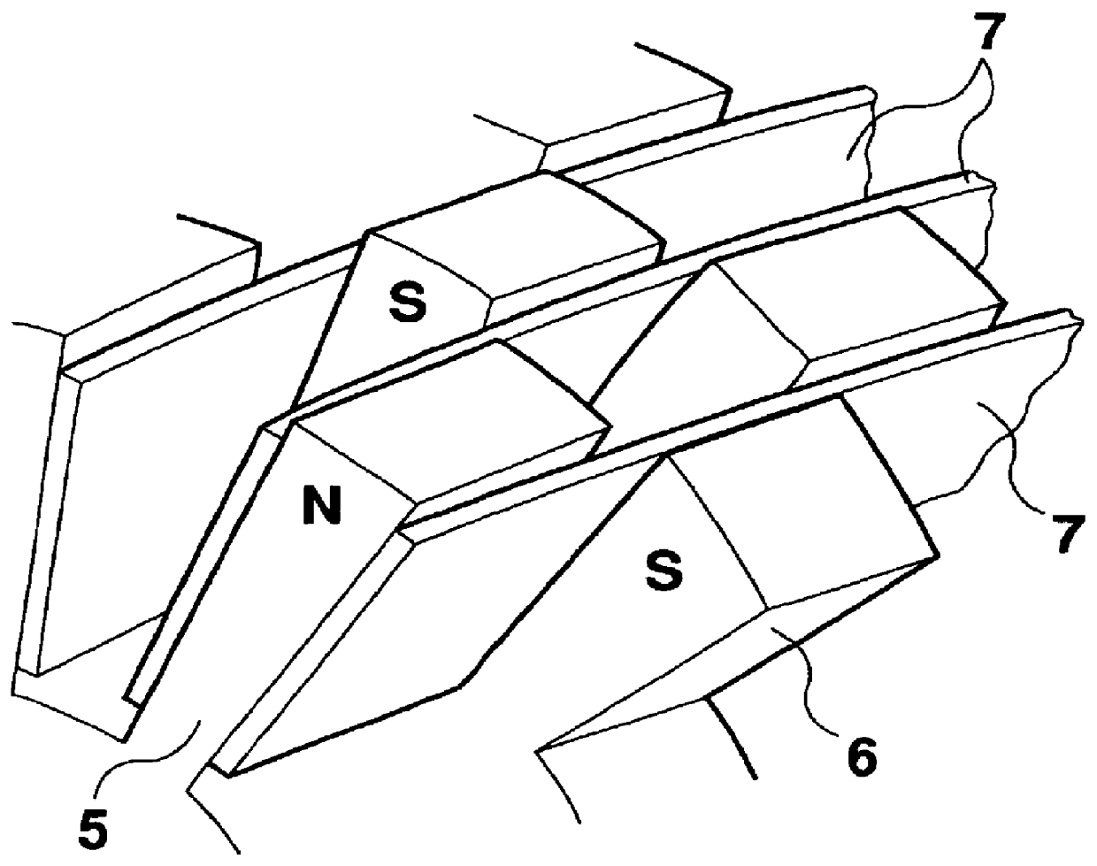
The structure of a stator and rotor incorporated in a permanent magnet motor in accordance with an embodiment of this invention is shown in FIG. 1. The stator indicated by numeral 1 is laminated with electromagnetic steel in the axial direction and provided with 18 slots indicated by marks from S1 to S18. A bipolar three-phase alternating current winding, commonly used for an induction motor, is looped through each slot. Teeth of the stator are formed so that the width of each front end is almost equal to the width of each slot inlet. Therefore, magnetic reluctance changes noticeably at regular intervals in a direction of stator rotation viewed from the rotor. The rotor has a slightly complicated shape wherein 17 sets of the north pole and the south pole are placed around the perimeter. Materials and basic structure of the rotor are constructed in much the same fashion as the stator wherein electromagnetic steel is laminated in the axial direction but the electromagnetic steel is no...


PUM


Abstract

The object of the present invention is to increase torque generation of a motor, to minimize a motor size, and to reduce a motor cost by improving a magnetic circuit of a rotor. In order to achieve the object and make effective use of the power of each permanent magnet within the entire motor, the present invention provides a motor comprising magnetic circuits for the pole N 5 commonly connected to the north pole of permanent magnets 7, magnetic circuits for the pole S 6 commonly connected to the south pole of permanent magnets 7. Also, the motor further comprises magnetic poles N in the shape of protruding poles of the north pole and the magnetic poles S in the shape of protruding poles of the south pole. The magnetic poles N, forming a part of the magnetic circuits for the pole N, are placed on a part around the perimeter of the rotor, and the number R of the magnetic poles N is different from the number m of stator poles. The magnetic poles S, forming a part of the magnetic circuit for the south pole, are placed on a part around the perimeter of the rotor alternately in a rotational direction of the rotor with the magnetic poles N in the shape of protruding poles of the north pole and the number of the magnetic poles S is R.

Description

1. Field of the InventionThe present invention generally relates to a vernier type motor having permanent magnets placed on a rotor thereof, and more particularly to an improved rotor structure of the vernier type motor.2. Description of the Related ArtFIG. 11 shows a relationship between a stator and a rotor of a conventional vernier type motor having permanent magnets placed on the rotor. Numeral 1 indicates the stator and marks from S1 to S18 indicate slots. A bipolar three-phase alternating current winding, commonly used for such an induction motor, is looped through each slot. Teeth of the stator are formed so that the width of each front end is almost equal to the width of each of the inlets of the slots. Therefore, magnetic reluctance noticeably changes at regular intervals in a direction of stator rotation viewed from the rotor. Numeral 2 indicates the rotor and 17 poles of permanent magnets are equally spaced around the perimeter of the rotor as shown in the figure. Numeral...

Claims


Application Information

Patent Timeline
IPC IPC(8): H02K21/16H02K21/14H02K1/27H02K29/00
CPCH02K1/2706H02K1/2713H02K1/2773H02K21/14H02K21/16H02K15/02
Inventor NASHIKI, MASAYUKI
Owner OKUMA CORP
Why Eureka
Try Eureka