Rapid computation of local eye vectors in a fixed point lighting unit

a fixed point lighting unit and local eye vector technology, applied in computing, digital computers, instruments, etc., can solve the problems of large processing capacity of applications which display three-dimensional graphics, difficult to achieve the effect of achieving the effect of difficult to achieve the effect of achieving the effect of achieving the effect of achieving the effect of reducing the size of the required hardwar

Inactive Publication Date: 2000-01-11
ORACLE INT CORP
View PDF4 Cites 84 Cited by
  • Summary
  • Abstract
  • Description
  • Claims
  • Application Information

AI Technical Summary

Problems solved by technology

The problem of visual realism, however, is quite complex.
Applications which display three-dimensional graphics require a tremendous amount of processing capabilities.
One constraint on prior art lighting units is the use of floating point arithmetic.
A major disadvantage of floating point arithmetic, however, is that the required hardware is relatively expensive in terms of size.
This is problematic for lighting units in lower-cost graphics systems seeking to maximize performance, particularly in view of the fact the majority of lighting operations do not require the full range of floating point math.
This is done because the calculation of the local

Method used


Image

  • Rapid computation of local eye vectors in a fixed point lighting unit
  • Rapid computation of local eye vectors in a fixed point lighting unit
  • Rapid computation of local eye vectors in a fixed point lighting unit

Examples


Embodiment Construction

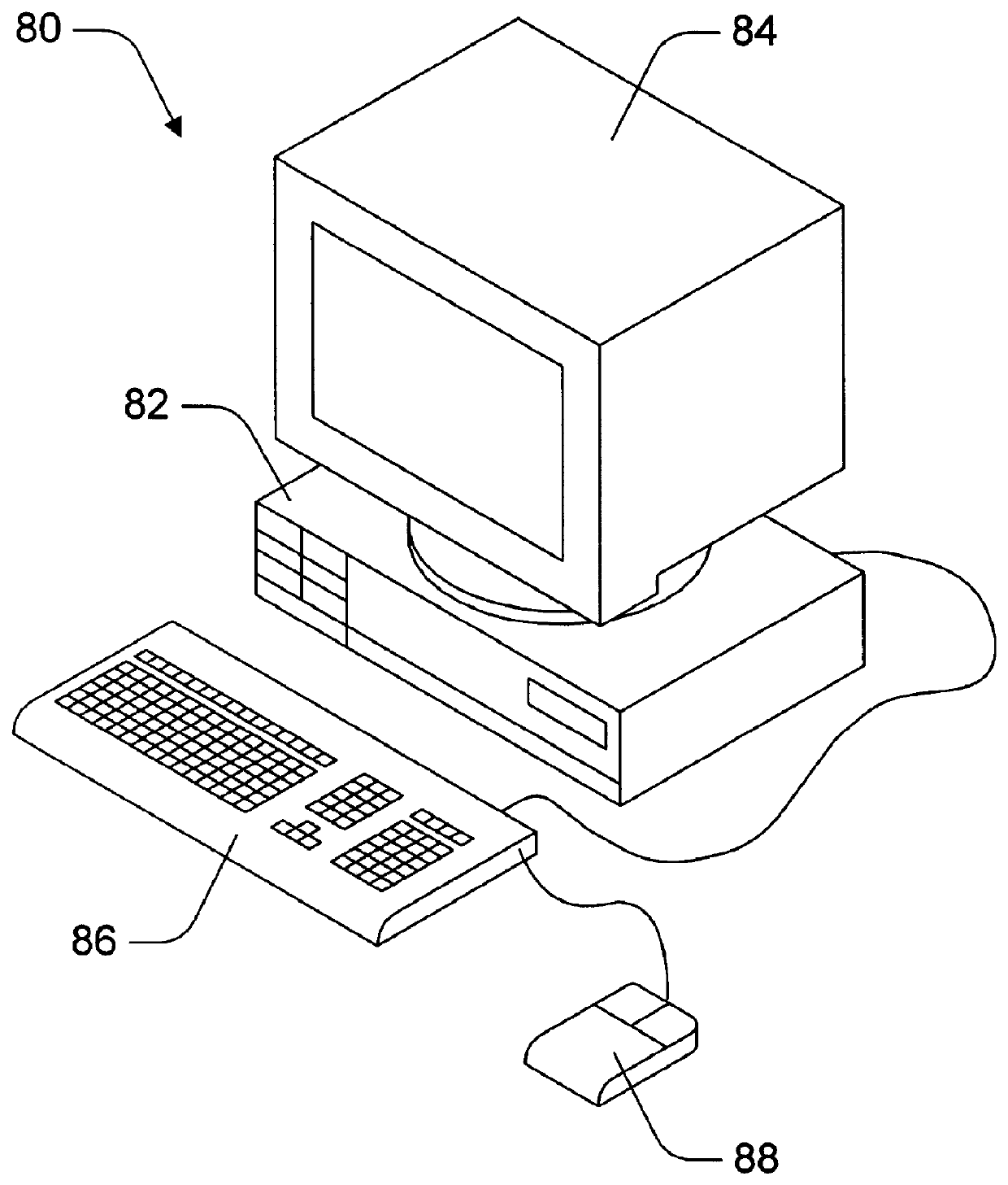
FIG. 1--Computer System

Referring now to FIG. 1, a computer system 80 which includes a three-dimensional (3-D) graphics accelerator according to the present invention is shown. As shown, the computer system 80 comprises a system unit 82 and a video monitor or display device 84 coupled to the system unit 82. The display device 84 may be any of various types of display monitors or devices. Various input devices may be connected to the computer system, including a keyboard 86 and / or a mouse 88, or other input. Application software may be executed by the computer system 80 to display 3-D graphical objects on the video monitor 84. As described further below, the 3-D graphics accelerator in computer system 80 includes a fixed point lighting unit which is configured to perform rapid computation of normalized local eye vectors for calculation of specular highlights corresponding to infinite light sources. The use of these local eye vectors results in more realistic lighting effects of graphi...


PUM


Abstract

A rapid method for calculating a local eye vector in a fixed point lighting unit. For a given triangle primitive which is to be projected into a given viewport in screen space coordinates, the local eye vector corresponds to a given eye position and a first vertex of the given triangle primitive. (A different local eye vector is calculated for each vertex of the given triangle primitive). The method first comprises generating a view vector matrix which corresponds to the given eye position and corner coordinates of the given viewport, where the corner coordinates are expressed in screen space coordinates. The view vector matrix is usable to map screen space coordinates to an eye vector space which corresponds to the given viewport. The method next includes receiving a first set of coordinates (in screen space) which correspond to the first vertex. The first set of coordinates are then scaled to a numeric range which is representable by the fixed point lighting unit. Next, the first set of coordinates are transformed using the view vector matrix, which produces a non-normalized local eye vector within the eye vector space for the given viewport. The non-normalized local eye vector is normalized to form a normalized local eye vector. The normalized local eye vector is then usable to perform subsequent lighting computations such as computation of specular reflection values for infinite light sources, producing more realistic lighting effects than if an infinite eye vector were used. These more realistic lighting effects do not come at decreased performance, however, as the local eye vector may be calculated rapidly using this method.

Description

The present invention relates to a 3-D graphics accelerator, and more particularly to a fixed point lighting unit within the 3-D graphics accelerator which performs rapid computation of local eye vectors.DESCRIPTION OF THE RELATED ARTA three dimensional (3-D) graphics accelerator is a specialized graphics rendering subsystem for a computer system which is designed to off-load the 3-D rendering functions from the host processor, thus providing improved system performance. In a system with a 3-D graphics accelerator, an application program executing on the host processor of the computer system generates three dimensional geometry data that defines three dimensional graphics elements for output on a display device. The application program causes the host processor to transfer the geometry data to the graphics accelerator. The graphics accelerator receives the geometry data and renders the corresponding graphics elements on the display device.One of the goals of many computer graphics s...

Claims


Application Information

Patent Timeline
IPC IPC(8): G06T15/00G06T15/50
CPCG06T15/005G06T15/50G06T15/506G06T17/00
Inventor NELSON, SCOTT R.DEERING, MICHAEL F.
Owner ORACLE INT CORP
Why Eureka
Try Eureka