Motor vehicle occupant sensing systems

a technology for sensing systems and motor vehicles, applied in vehicular safety arrangements, electric devices, process and machine control, etc., can solve problems such as considerable variation in passenger acceleration and passenger injury seriousness

Inactive Publication Date: 2000-01-11
METHODE ELETRONICS INC
View PDF87 Cites 255 Cited by
  • Summary
  • Abstract
  • Description
  • Claims
  • Application Information

AI Technical Summary

Problems solved by technology

For example, if the passenger is seated too far forward, or has his / her head too far forward, occupying the space into which the air bag will deploy, the passenger may be seriously injured by the deployment of the air bag intended to prevent passenger injury.
But even if the passenger is not too far forward at the beginning of the collision, the passenger will tend to move rapidly forward, with the passenger's head leading that motion, relative to the vehicle, as the vehicle rapidly decelerates, and will tend to move into the air bag deployment space, at least in the case of forward collisions, and may be too far into the air bag deployment space, before the completion of air bag deployment, to escape injury from the air bag deployment.
Also variation of the crash intensity by itself will cause considerable variation in passenger acceleration.

Method used


Image

  • Motor vehicle occupant sensing systems
  • Motor vehicle occupant sensing systems
  • Motor vehicle occupant sensing systems

Examples


Embodiment Construction

)

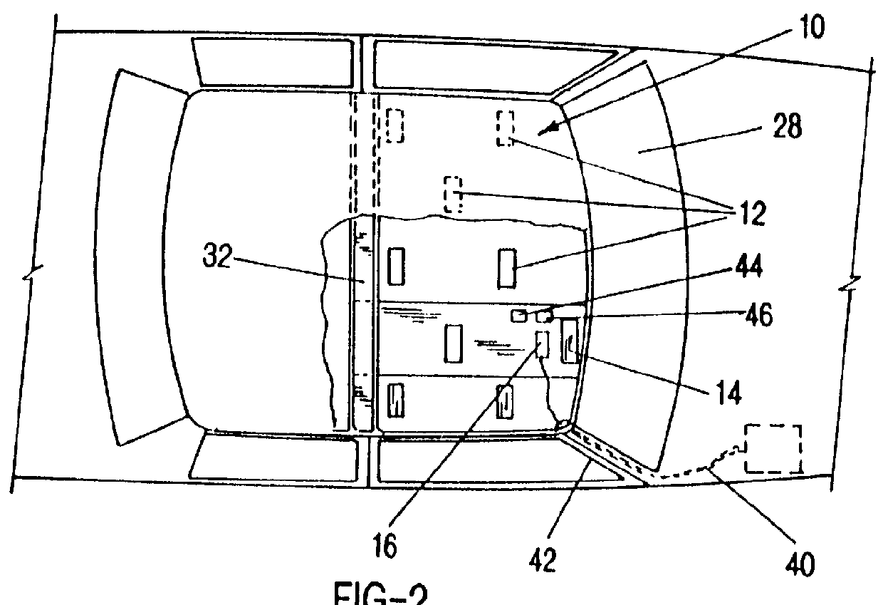
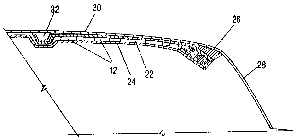
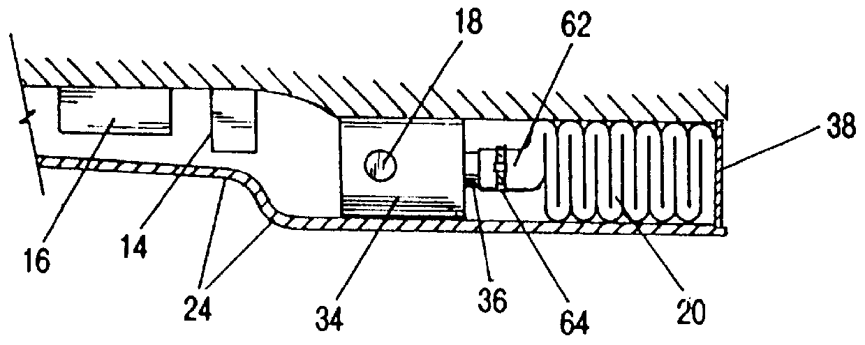
Referring now to the drawings, in which like reference numbers denote like or corresponding elements, the principal components of the roof--mounted air bag system of the present invention, are a position sensor array 10 of capacitive coupling proximity sensors 12, a rollover sensor 14, a microprocessor 16 (which may be analog or digital or a hybrid thereof), a gas generator means 18, and an air bag 20, each further discussed below.

The components of the system are attached to a mounting plate 22 above the headliner 24 which is held in place against the passenger cabin roof by edge molding, adhesives, and / or fasteners. The mounting plate 22 is secured by bolts or other secure attachment means at its front end, to the windshield header 26, a part of the vehicle used to attach the windshield 28 to the forward edge of the vehicle roof 30. The mounting plate 22 is firmly secured at its rear end, e.g., by bolts or welding, to a cross brace 32, a standard brace which extends transversely a...


PUM


Abstract

A roof-mounted passenger position sensor array of capacitive coupling passenger position sensors, to determine position and motion of a passenger by analysis of distances of the passenger to the various sensors of the array and analysis of the changes of distances with time.

Description

1. Field of the Invention (Technical Field)The present invention concerns systems for sensing characteristics of motor vehicle occupants for purposes such as deployment of air bags during vehicle crashes. More particularly it concerns systems in which the system operation is affected not only by information about the motion of the vehicle caused by crash forces, including angular acceleration, but also measured data concerning the motion of the passenger, so that the system will operate in a manner to minimize the risk of serious injury to the passenger, and will not operate when the air bag deployment would not likely be beneficial.2. Background ArtAutomobile air bag systems are a well known means of attempting to reduce the likelihood of serious injury to passengers in collisions. These systems are designed to very quickly inflate an air bag in front of a passenger during a collision, so as to hopefully prevent the passenger from colliding with hard objects in the passenger compar...

Claims


Application Information

Patent Timeline
Patent Type & Authority Patents(United States)
IPC IPC(8): B60N2/00B60R21/01G01V3/08B60R21/16B60N2/90B60R21/013B60R21/015B60R21/055B60R21/213B60R21/232B60R21/233G01B7/00G08B21/06
CPCB60N2/002B60R21/013B60R21/213B60R21/233G01V3/088G08B21/06B60R21/01532B60R21/0154B60R21/232B60R2021/01006B60R2021/01306B60R2021/23324
Inventor KITHIL, PHILIP W.BARRON, MICHAEL H.MCINTOSH, WILLIAM C.
Owner METHODE ELETRONICS INC
Why Eureka
Try Eureka