Sensor fault detection system

a fault detection and sensor technology, applied in the field of sensor fault detection system, can solve the problems of inability to obtain a model of a complicated system, inability to completely eliminate, and extra weight of sensors and associated electronics

a fault detection and sensor technology, applied in the field of sensor fault detection system, can solve the problems of inability to obtain a model of a complicated system, inability to completely eliminate, and extra weight of sensors and associated electronics

US6016465AInactive Publication Date: 2000-01-18QINETIQ LTD

Image

  • Sensor fault detection system
  • Sensor fault detection system
  • Sensor fault detection system

Examples


Embodiment Construction

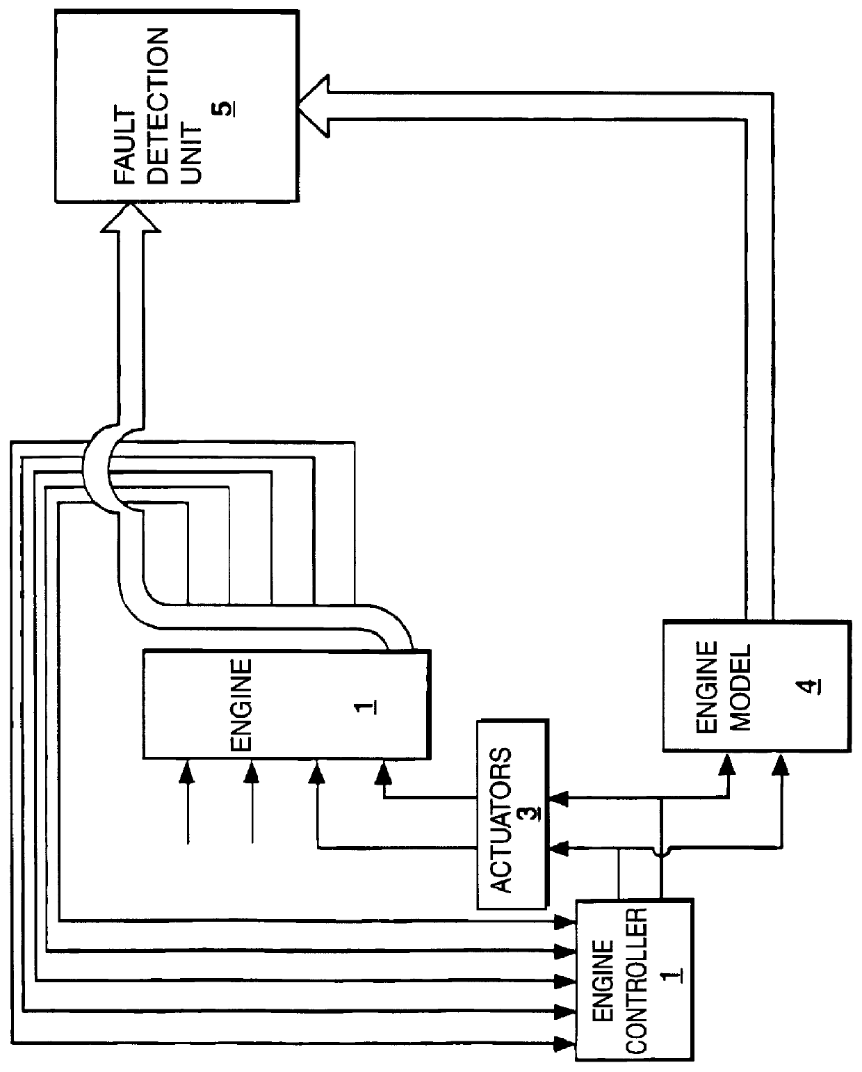
FIG. 1 shows an embodiment of the sensor fault detector applied to an aero-engine. The complete system comprises the aero-engine (1) which is to be monitored and controlled and to which various sensors are fitted for measuring parameters such as high pressure spool speed, low pressure spool speed, high pressure compressor temperature, high pressure compressor pressure etc. Some of the signals from these sensors, including low and high pressure spool speeds, are input into an engine controller (2). In addition, the engine controller has three inputs arising from outside manual control: fuel flow, nozzle area and intermediate pressure blow-off valve position. The engine controller dictates the operating conditions of the engine by giving signals to actuators (3) which act on the engine. The engine controller signals are also delivered to an engine model (4) which is a software model of the engine characteristics. This engine model provides reference signal values, these being determin...


PUM


Abstract

The sensor fault detector is one in which each sensor signal is compared with a reference signal provided by e.g. a model of the system being monitored. Prior art sensor fault detectors subtract the output of the sensor and the corresponding reference signal from each other, and a fault is declared when the residual difference exceeds a prescribed threshold. However, modelling errors (such as scaling discrepancies), d.c bias and noise mean that faults are often wrongly declared, or alternatively that only large faults can be detected. These problems are overcome according to the invention by comparing the "shape" of the sensor signal with that of the corresponding reference signal (i.e. comparing the signal outlines) over a finite time window, using e.g. correlation techniques. A fault is declared when the shapes differ by a prescribed amount.

Description

1. Field of the InventionThis invention relates to an improved system for detecting sensor faults in systems which rely on sensors for monitoring and control purposes. An example of this is the detection of faults in sensors used to control gas turbine engines.2. Discussion of Prior ArtSensors which measure gas turbine engine parameters have been shown to be one of the most fault prone components in such engine control systems. Attempts to improve sensor integrity have concentrated on maintaining correct sensor readings, even in the event of one or more sensor faults. It is known in the art to overcome the problem of sensor faults by doubling or even trebling the number of sensors. This duplication of components is referred to as "hardware redundancy", which means that if a fault arises in one of the sensors, its presence is indicated by virtue of the two sensor signals being dissimilar. Although this method is widely used, it is not only costly, but more importantly in aerospace ap...

Claims


Application Information

Patent Timeline
18 Jan 2000
Publication
US6016465A
IPC
G05B9/02
CPC
G05B9/02; G05B23/0235
Inventors
KELLY, RONALD W