Manufacturing method and apparatus of steel cord for rubber product reinforcement

a technology of steel cords and rubber products, which is applied in the direction of yarn, continuous wounding machines, transportation and packaging, etc., can solve the problems of not being able to fully function as a reinforcing material, the life of the rubber composite itself falling, and the inability to disclose a manufacturing method of steel cords

Inactive Publication Date: 2000-01-25
TOKYO ROPE MFG
View PDF6 Cites 29 Cited by
  • Summary
  • Abstract
  • Description
  • Claims
  • Application Information

AI Technical Summary

Problems solved by technology

These steel cords are generally made by twisting together a plurality of steel wires, but if they are not well integrated with the rubber matrix they cannot function fully as a reinforcing material.
Also, when the rubber matrix does not penetrate well into the inside of the steel cord, water enters spaces inside the steel cord not filled by the rubber matrix, and as a result corrosion spreads and the life of the rubber composite itself also falls.
However, in this related art, there is no disclosure of a method for manufacturing a steel cord having these characteristics.
However, with methods that use a tubular twisting machine there has been the major problem that productivity is poor and the product cost consequently is high.
Because of this, the sectional shape of the steel cord collapses and the flat faces (the major axis sides) fail to align in a fixed direction and the gaps between the sheath filaments become non-uniform, and as a result stability of shape, which is an important characteristic of a steel cord, is lost and also the rubber penetration becomes unstable.
Con...

Method used


Image

  • Manufacturing method and apparatus of steel cord for rubber product reinforcement
  • Manufacturing method and apparatus of steel cord for rubber product reinforcement
  • Manufacturing method and apparatus of steel cord for rubber product reinforcement

Examples


first preferred embodiment

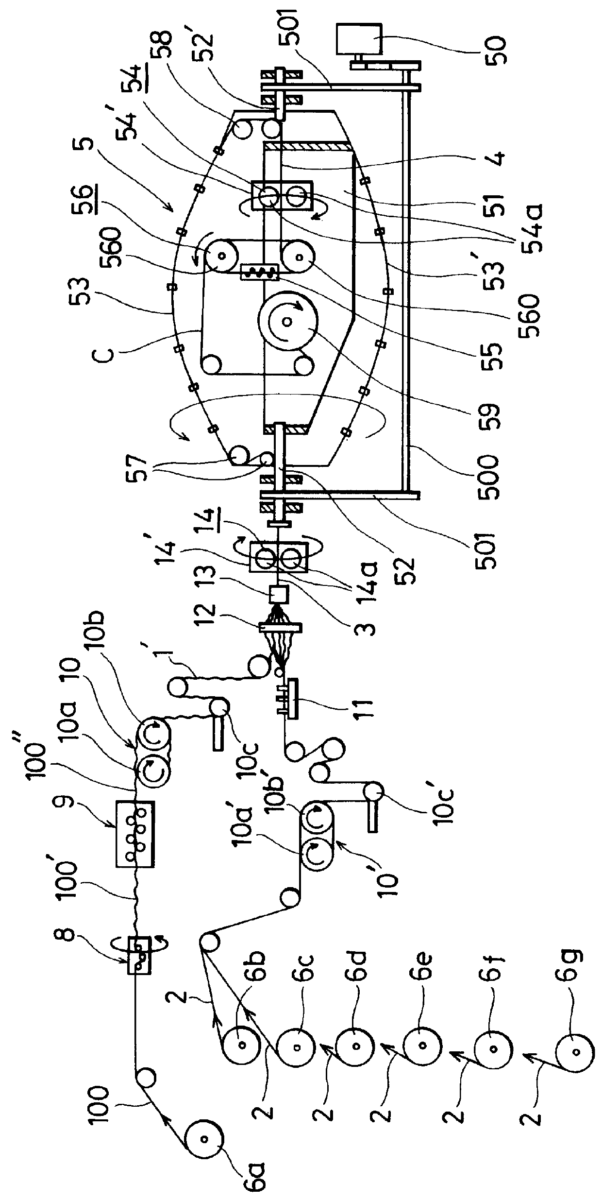
Using a core filament of diameter 0.35 mm and six sheath filaments of the same diameter, a flat steel cord of 1+6 structure was manufactured.

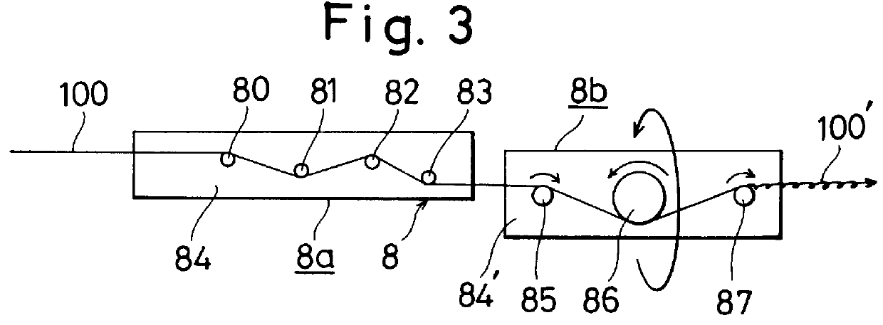
As the helical wave preformer, a preformer of the construction shown in FIG. 2 was used. Carbide pins of diameter 2 mm were used for the four pins, and these were disposed on the base with a shaft spacing of 4.0 mm (and an offset of 0.25 mm) in a zigzag and rotatably supported by bearings.

As the sheath filament preformer, a preformer of the construction shown in FIG. 5 was used. With a common base, three carbide pins of diameter 2 mm were used for each filament, and these were disposed on the base with a shaft spacing of 7.5 mm (and an offset of 0.25 mm) in a zigzag and rotatably supported by bearings.

As the first flattener and the second flattener, seven carbide rollers of diameter 16 mm were mounted with a uniform spacing of 21 mm in a first base (90 in FIG. 4) of a pair of facing bases, and eight of the same rollers were mounted with a unifo...

second preferred embodiment

Using one core filament of diameter 0.35 mm and six sheath filaments of the same diameter, a flat steel cord of 1+6 structure was manufactured.

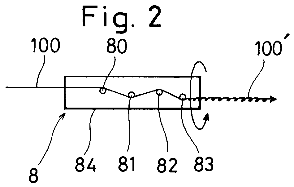
In this preferred embodiment, as the helical wave preformer, the preformer shown in FIG. 3 was used. For the wave preforming part, a part having the same specifications as the helical wave preformer of the first preferred embodiment was used. For the twisting part, rollers of diameter 16 mm were used as the entrance side roller and the exit side roller, and these were rotatably mounted on a base by means of bearings. A roller of diameter 40 mm was used as the central roller, and this was also rotatably mounted on the base by means of a bearing. The core filament was led from the entrance side roller and wound twice around the central roller before being led to the exit side roller. This twisting part was rotated on the pass line in the same direction as the twisting machine proper at a speed of 5.2 times that of the twisting machine proper.

Ot...

third preferred embodiment

Using one core filament of diameter 0.30 mm and five sheath filaments of diameter 0.35 mm, a flat steel cord of a 1+5 structure was manufactured.

In this preferred embodiment, as the helical wave preformer, the preformer shown in the second preferred embodiment was used with the same conditions as in the second preferred embodiment. The push-in Ro in the first flattener was made 3.3 mm, and the push-in Ro in the second flattener was made 1.7 mm.

Otherwise the conditions of this third preferred embodiment were made the same as those of the first preferred embodiment.


PUM

PropertyMeasurementUnit
Angleaaaaaaaaaa
Diameteraaaaaaaaaa
Lengthaaaaaaaaaa

Abstract

A method for using a bunching type twisting machine to manufacture a steel cord made up of one core filament having a continuous wavy form and five to eight sheath filaments not having a wavy form disposed around the core filament, the cross-sectional shape of the cord forming an ellipse whose orientation is substantially constant in the length direction of the cord. After a core filament is preformed with a helical wavy form of a smaller pitch than the cord twisting pitch, this is squashed to form a flat helical core filament at a stage before it is twisted together with sheath filaments, and then sheath filaments are twisted around this flat helical core filament to make an intermediate product cord and this intermediate product cord is then squashed and thereby flattened before being taken up on a reel.

Description

1. Field of the InventionThe present invention relates to a method and apparatus for manufacturing a steel cord of a specified structure for use as a reinforcing material of rubber products such as radial vehicle tires and conveyor belts.2. Description of the Related ArtSteel cords are commonly used as a reinforcing material in rubber products such as radial vehicle tires and conveyor belts.These steel cords are generally made by twisting together a plurality of steel wires, but if they are not well integrated with the rubber matrix they cannot function fully as a reinforcing material. Also, when the rubber matrix does not penetrate well into the inside of the steel cord, water enters spaces inside the steel cord not filled by the rubber matrix, and as a result corrosion spreads and the life of the rubber composite itself also falls.To solve this kind of problem, in Japanese Patent Publication No. H.5-186978 there is disclosed a steel cord of a 1+6, 1+7 or 1+8 structure which compri...

Claims


Application Information

Patent Timeline
IPC IPC(8): D07B1/06D07B3/10D07B1/00D07B3/00D07B7/00D07B7/02
CPCD07B1/0653D07B3/10D07B7/025B60C9/0057D07B7/027D07B2201/2007D07B2201/2008D07B2201/2018D07B2201/2023D07B2207/205D07B2501/2046D07B2501/2076D07B2801/12D07B2801/14D07B2201/2019D07B2207/4072D07B2207/4018
Inventor KAWATANI, HIROSHISUZUKI, SHIGERU
Owner TOKYO ROPE MFG
Why Eureka
Try Eureka