Mobile track vehicle

a technology for track vehicles and vehicles, applied in the direction of locomotives, transportation and packaging, retractable wheels, etc., can solve the problems of prior art vehicles with increasingly difficult maneuverability problems, conversion problems, and inability to allow the roadway to the railway conversion, so as to increase the starting traction, and improve the effect of safety

Inactive Publication Date: 2000-02-08
KERSHAW JR ROYCE G
View PDF10 Cites 47 Cited by
  • Summary
  • Abstract
  • Description
  • Claims
  • Application Information

AI Technical Summary

Benefits of technology

Another object of the present invention is to produce a significant advantage over other types of road / rail vehicles by producing a system which when it is in rail travel configuration, 100 percent of the vehicle's weight can be carried on the rail wheels which are powered and braked thereby allowing higher and safer rail speeds.
It is also an object of the present invention to produce a vehicle which provides enhanced operability when converting from road to rail by maneuvering into a position parallel to the track at a road crossing or a yard.
Still another object of the present invention is to produce a mounted turntable mounted at the center of gravity of the vehicle which allows the vehicle to convert at a narrow road crossing.
It is also an object of the present invention to increase the starting traction by extending the concomitantly powered road axle so that the inner rubber tires contact the rail and the high traction of rubber on rail can assist in overcoming the inertial resistance of a massive body at rest such as a train or string of cars.
These and other features and advantages of the invention are accomplished by the unique combination of features which are utilized to provide motive power to the drive wheels and to maneuver the vehicle selectively between road and track. More specifically, the present invention utilizes a single transmission to couple the engine to the drive wheels and a single output drive shaft which is coupled to both the driven road wheels and driven rail wheels through a pass through differential and a terminal differential respectively. Accordingly, superior performance, particularly at starting is achieved because both sets of drive wheels may be employed for concomitant rotation. Further track to road conversion is readily accomplished through the use of a pedestal type lift which allows the vehicle to be rotated about a vertical axis to a position displaced by ninety degrees.

Problems solved by technology

However, prior art road and rail vehicles lack the ability to allow the roadway to railway conversion absent placing the vehicle parallel to the desired railway or roadway.
Moreover, narrow road crossings present prior art vehicles with increasingly difficult maneuverability problems.
Moreover, there exists a need for a vehicle which has improved operational characteristics thereby allowing it to convert from the roadway to the railway position at narrow crossings which would create conversion problems otherwise.

Method used


Image

  • Mobile track vehicle
  • Mobile track vehicle
  • Mobile track vehicle

Examples


Embodiment Construction

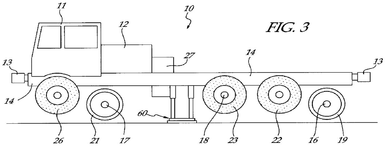
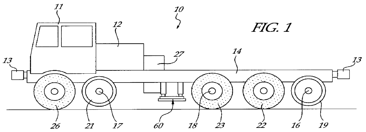
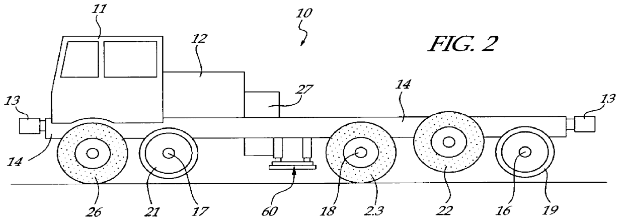
Referring to the drawings for a better understanding of the function and structure of the invention, it may be seen that the improved self-propelled mobile track vehicle (MTV) is indicated generally by the number 10 as shown in FIGS. 1-8. The mobile track vehicle may be in the general form of a conventional roadway truck 10 having a operator cab 11, a diesel engine 12, an automatic chassis coupler 13, a chassis 14, a suspension system indicated generally by number 15 connected to the chassis 14 which supports conventional rail wheel axles 16, 17 and powered road wheel axle 18. As shown in FIG. 6, it will be understood that this drive assembly is capable of simultaneously driving both the rail wheels 19, 21, and road wheels 23. Actuators 53, 54, 56, 57, 58 will allow the driver to selectively engage the rail wheels 19, 21 or the road wheels 22, 23, 26 or a combination of rail wheels and road wheels with the desired driving surface.

The means for selectively driving both the road wheel...


PUM


Abstract

An improved self-propelled mobile track vehicle (MTV) capable of traveling by road at normal highway speeds and traveling by rail after conversion at a narrow railroad crossing by producing a device for rotating the vehicle 90 degrees. The vehicle is powered by a diesel engine driving through a power shift transmission to the roadway and railway axles. A significant advantage over other types of road / rail vehicles is that 100 percent of the vehicle's weight is carried on the rail wheels, which are powered and braked, thereby allowing higher and safer rail speeds. One way to convert the vehicle from roadway travel to railway travel is to maneuver it into a position parallel to the track at a road crossing. The rail axles are then extended and road axles retracted. In addition, a turntable mounted at the vehicle's center of gravity also allows the vehicle to convert at a narrow road crossing. While at railway / roadway crossing the unit raises and rotates 90 to align with the desired roadway or railway. The vehicle can assist in starting a train by extending the powered road axle so that the inner rubber tires contact the rail and the high traction of rubber on rail assists in increasing starting traction of the vehicle thus allowing the vehicle to assist in starting a train.

Description

The present invention generally relates to railway and roadway self-propelled vehicles. More particularly, it relates to an improved self-propelled mobile track vehicle (MTV) capable of traveling by road at normal highway speeds and traveling by rail after conversion at a narrow railroad crossing by producing a means for rotating the vehicle ninety degrees.BACKGROUND OF INVENTIONSelf-propelled vehicles which are operable on either roadways or highways are widely known and used in the rail industry. For instance, U.S. Pat. No. 3,019,742 discloses a universal mobile unit for self propulsion on either highways or railways which embodies a source of power for motivation of various instrumentalities and one in which is so constructed and arranged as to provide for the selective attachment, support and conveyance of such various types of maintenance equipment so the one unit may be universally applicable for carrying out a wide variety of maintenance and construction operations. Moreover,...

Claims


Application Information

Patent Timeline
Patent Type & Authority Patents(United States)
IPC IPC(8): B60F1/04B60F1/00B61D15/00
CPCB60F1/043B61D15/00B60F2301/10
Inventor KERSHAW, JR., ROYCE G.
Owner KERSHAW JR ROYCE G
Why Eureka
Try Eureka