Vibrating gyroscope and adjusting method therefor

a vibrating gyroscope and adjusting method technology, applied in the direction of acceleration measurement using interia force, turn-sensitive devices, instruments, etc., can solve the problems of degrading the s/n ratio of the vibrating gyroscope, unable to obtain the stable signal resulting from the coriolis force, and unstable vibration of the vibrator

Inactive Publication Date: 2000-02-15
MURATA MFG CO LTD
View PDF8 Cites 19 Cited by
  • Summary
  • Abstract
  • Description
  • Claims
  • Application Information

AI Technical Summary

Problems solved by technology

However, the above known type of vibrating gyroscope and the adjusting method therefor present the following problems.
The vibration of the vibrator thus becomes unstable, and the S / N ratio of the vibrating gyroscope is degraded.
As a result, a stable signal resulting from the Coriolis force cannot be obtained.
This method, therefore, cannot solve the above-described problems.
Accordingly, in this vibrating gyroscope 100, there is a great phase delay in the detection signal, thus causing low output response characteristics.
In practice, the lateral surface is difficult to etch depending on the shape of the base.

Method used


Image

  • Vibrating gyroscope and adjusting method therefor
  • Vibrating gyroscope and adjusting method therefor
  • Vibrating gyroscope and adjusting method therefor

Examples


Embodiment Construction

)

Hereinafter, the preferred embodiments of the present invention are explained in detail with reference to the drawings.

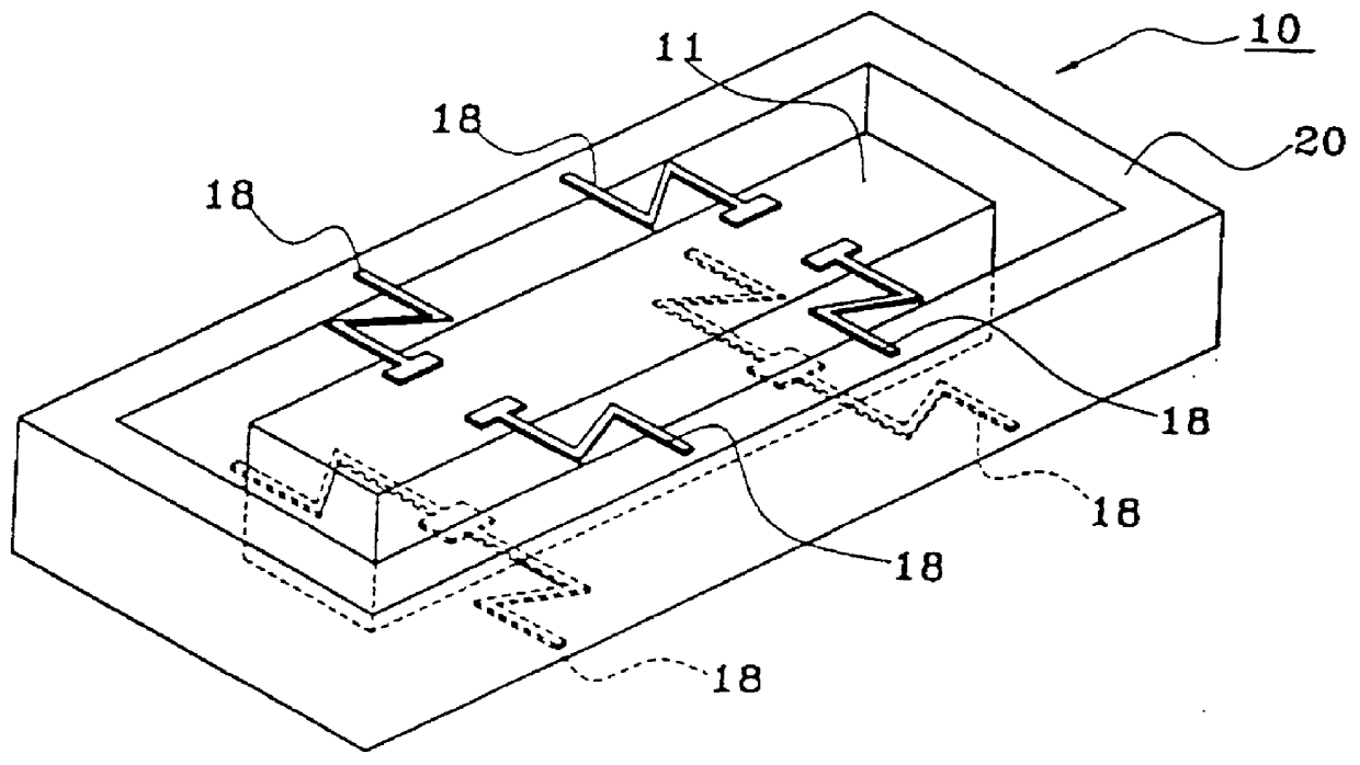
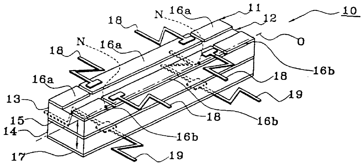
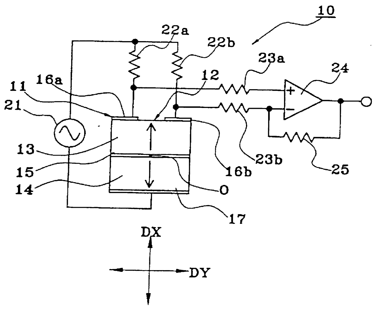
FIG. 1 illustrates a vibrating gyroscope according to a first embodiment of the present invention. The vibrating gyroscope 10 includes a vibrator 11. The vibrator 11 has a vibrating member 12 having a general square prism shape. The vibrating member 12 has a first piezoelectric substrate 13 and a second piezoelectric substrate 14, both of which are made from PZT (lead zirconate titanate) and are stacked with an intermediate electrode 15 interposed therebetween. The first piezoelectric substrate 13 and the second piezoelectric substrate 14 are polarized in mutually opposite directions along their thickness, as indicated by the arrows shown in FIG. 1.

Two divided electrodes 16a and 16b are formed parallel to each other in the longitudinal direction of the vibrating member 12 on one main surface of the first piezoelectric substrate 13, i.e., on the surface which does n...


PUM


Abstract

A vibrating gyroscope includes a columnar vibrator, a driver and a detector. The columnar vibrator includes first and second piezoelectric substrates polarized in mutually opposite directions along the thickness directions thereof and stacked with each other. Two divided electrodes are formed on one main surface of the first piezoelectric substrate and spaced in the direction perpendicular to the longitudinal direction of the first piezoelectric substrate, and a common electrode is formed on one main surface of the second piezoelectric substrate. The driver drives the vibrator in the thickness direction of the first and second piezoelectric substrates and is connected between the divided electrodes and the common electrode. The detector detects a displacement caused by bending vibration of the vibrator, and is connected to the divided electrodes. The vibrator has substantially the same resonant frequency in the two diagonal directions which diagonally connect four edges elongating in the longitudinal direction of the vibrator.

Description

1. Field of the InventionThe present invention relates to a vibrating gyroscope, and more particularly to a vibrating gyroscope used in a video camera or the like to detect external vibrations such as hand shaking by detecting a rotational angular velocity and cancel out the vibrations on the basis of the detected information. The invention also relates to a method for adjusting the above type of vibrating gyroscope.2. Description of the Related ArtFIG. 9 shows one example of the vibrating gyroscopes disclosed in Japanese Laid-Open Patent Publication No. 7-332988. This gyroscope is explained hereinbelow with reference to the drawings.Referring to FIG. 9, a vibrating gyroscope 100 includes a vibrator 101. The vibrator 101 has a vibrating member 102. The vibrating member 102 is integrally formed by stacking a first piezoelectric substrate 103 and a second piezoelectric substrate 104 with an intermediate electrode 105 therebetween. Two divided electrodes 106a and 106b are formed on the...

Claims


Application Information

Patent Timeline
Patent Type & Authority Patents(United States)
IPC IPC(8): G01C19/56G01C19/5663
CPCG01C19/5663
Inventor YABE, TORUMORITA, KATSUHIKOTATSUMI, TETSUOISHITOKO, NOBUYUKITAKENAKA, MICHIHIKO
Owner MURATA MFG CO LTD
Why Eureka
Try Eureka