Apparatus for controlling laser diode

Inactive Publication Date: 2000-02-15
LAPIS SEMICON CO LTD
View PDF7 Cites 11 Cited by
  • Summary
  • Abstract
  • Description
  • Claims
  • Application Information

AI Technical Summary

Benefits of technology

Accordingly, an object of the invention is to provide an apparatus that can control a laser diode without losing large amount of power.
Another object of the invention is to provide a laser module, in which a laser diode is controlled without losing large amount of power.
Still another object of the invention is to provide an optical amplifier, in which a laser diode, generating an exciting light, is controlled without losing large amount of power.

Problems solved by technology

However, some voltage is lost at the resistor; and therefore, it is difficult to drive the laser diode with small quantity of electric current.

Method used


Image

  • Apparatus for controlling laser diode
  • Apparatus for controlling laser diode
  • Apparatus for controlling laser diode

Examples


Embodiment Construction

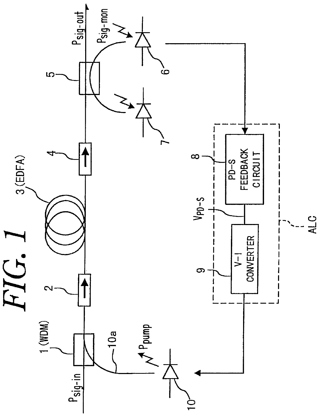
For better understanding of the invention, background technology is first described in conjunction with FIG. 1. FIG. 1 shows an apparatus for amplifying an input signal light P.sub.sig-in to provide an output signal light P.sub.sig-out having a constant power. The apparatus includes a WDM (Wavelength Division Multiplexer) 1 to which the input signal light P.sub.sig-in is supplied. The WDM 1 is connected at an output terminal to an input terminal of an isolator 2, of which an output terminal is connected to an input terminal of an EDFA (Erbium Doped Fiber optic Amplifier) 3.

The EDFA amplifies the input signal light P.sub.sig-in to provide the output signal light P.sub.sig-out. The EDFA 3 is connected at an output terminal to an input terminal of another isolator 4, of which an output terminal is connected to an input terminal of a photo coupler 5. The photo coupler 5 divides a signal supplied from the isolator 4 into two to provide the output signal light P.sub.sig-out and a monitor ...


PUM


Abstract

An apparatus for controlling a laser diode (135) includes a photodiode (136) which monitors an output light (Ppump) of the laser diode (135) and a control signal generator (132) which generates a control signal in response to an output of the photodiode (136). The apparatus also includes a driver circuit (134) which drives the laser diode (135) in response to the control signal so that the laser diode (135) generates a constant power of light.

Description

This application claims the priority of Application No. H09-107278, filed Apr. 24, 1997 in Japan, the subject matter of which is incorporated herein by reference.The present invention relates to an apparatus for controlling an output power of a laser diode, and more particularly, to such an apparatus used in an optical amplifier.A type of optical amplifier includes an EDFA (Erbium Doped Fiber optic Amplifier), which amplifies an input signal light to provide an output signal light having a constant power. The EDFA is excited with an excitation light generated by a laser diode, and the like. The input signal light is combined with the excitation light, and the combination light is supplied to the EDFA.In such an optical amplifier, it is important to control an output power of the laser diode in order to keep the output signal light being constant. For controlling the laser diode, it is required to detect electric current flowing through it precisely. According to a conventional techn...

Claims


Application Information

Patent Timeline
IPC IPC(8): H01S5/0683H01S5/00H01S5/042
CPCH01S5/0683
Inventor ITOU, TOHRU
Owner LAPIS SEMICON CO LTD
Why Eureka
Try Eureka