Method for radio resource control

a radio resource and control technology, applied in the field of sharing radio resources, can solve the problems of long data transmission delay, interference between adjacent cells,

Inactive Publication Date: 2000-02-29
NOKIA TECHNOLOGLES OY
View PDF16 Cites 347 Cited by
  • Summary
  • Abstract
  • Description
  • Claims
  • Application Information

AI Technical Summary

Benefits of technology

An object of the present invention is to introduce a method for a flexible and dynamic division of radio resources in the base station subsystem of a cellular radio network.

Problems solved by technology

One of the biggest challenges of the base station subsystem is to control the use of these physical radio resources so that all terminals located in the cell coverage are at any moment capable of receiving data transmission services of the requested quality, and that adjacent cells interfere with each other as little as possible.
A drawback is generally a longer data transmission delay, because after each pause, the transmission of a new packet requires the exchange of certain control or signalling messages between the mobile station and the base station.

Method used


Image

  • Method for radio resource control
  • Method for radio resource control
  • Method for radio resource control

Examples


Embodiment Construction

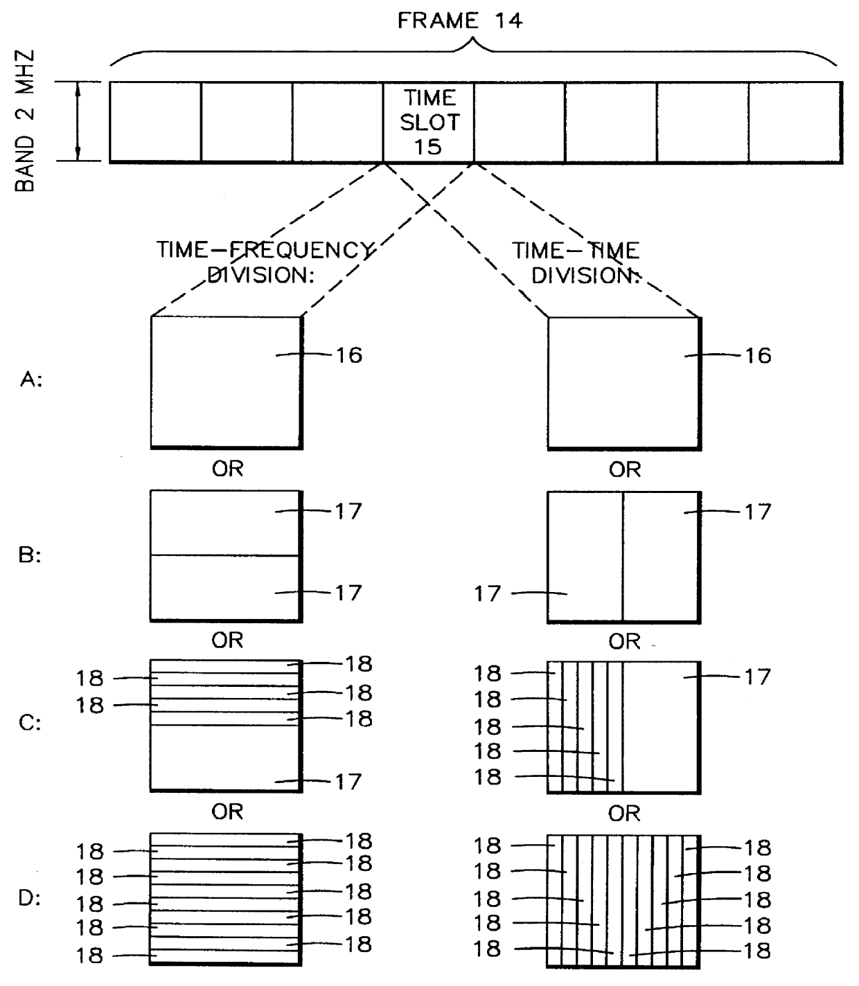
FIG. 2a illustrates a two-dimensional frame 14 according to a preferred embodiment of the invention. In the above description it was maintained that the first dimension of the frame is time and the second dimension can be either time, frequency or code. In the case of FIG. 2a, the second dimension of the frame 14 is frequency or time. The size of the frame in the direction of both dimensions must be chosen so that it is compatible with other specifications set for the system. In this example, the length of the frame in the time direction is about 4.615 milliseconds, and it is divided, in the time direction, into eight time slots, in which case the length of one time slot 15 is about 0.577 ms. The frame width in the frequency direction is about 2 MHz.

The smallest uniform structural elements of the frame, i.e. the slots, are various subdivisions of a time slot 15. In the lower left portion of FIG. 2a, time-frequency division is applied, whereby the chronological length of each slot is...


PUM


Abstract

In order to control the use of physical radio resources, the physical radio resources are divided into chronologically consecutive frames (14), so that a frame contains slots (16, 17, 18) of various sizes, which slots represent a given share of the physical radio resources contained in the frame and can be individually allocated to different radio connections. The first dimension of a frame is time and the second dimension can be time, frequency or code. In the direction of the second dimension the slots represent various sizes, and a given first integral number of slots of the first size can be modularly replaced by another integral number of slots of another size. A certain number of consecutive frames form a superframe (19), in which case frames with corresponding locations in consecutive superframes are equal in slot division and allocations, if the data transmission demands do not change. Changes in the state of occupancy of the slots are possible at each superframe. In order to form an uplink connection, the mobile station sends a capacity request, where it indicates the type of requested connection and the demand of resources. In order to form a downlink connection, the base station subsystem sends a paging call, where it indicates the location in the superframe of the slots allocated to the connection. In order to indicate the state of occupancy, the base station subsystem maintains a superframe-size parametrized reservation table.

Description

TECHNOLOGICAL FIELDThe invention relates generally to sharing radio resources between various users in a cellular radio system. Particularly the invention relates to sharing radio resources in a system where the users'data transmission needs, both in quality and quantity, change rapidly.At the moment of filing this application, the most general form of mobile personal telecommuication is a second-generation digital cellular radio network; these networks include the European systems GSM (Global system for Mobile telecommunications) and its extension DCS1800 (Digital Communications System at 1800 MHz), the North American (USA) systems IS-136 (Interim Standard 136), IS-95 (Interim Standard 95) and the Japanese system PDC (Personal Digital Cellular). These systems transmit mainly speech, telefaxes and short text messages, as well as digital data at a limited speed, for instance files transmitted between computers. Several third-generation systems are being designed, the aims being world...

Claims


Application Information

Patent Timeline
Patent Type & Authority Patents(United States)
IPC IPC(8): H04B7/26H04Q7/38H04L12/56H04W28/06H04W68/00H04W72/00H04W72/04H04W74/04H04W99/00
CPCH04B7/2656H04W72/0446H04W28/06H04W28/26H04W48/08H04W68/00H04W74/04H04W76/02H04W84/042H04W76/10
Inventor RIKKINEN, KARIAHMAVAARA, KALLERINNE, MIKKORINNE, MIKA
Owner NOKIA TECHNOLOGLES OY
Why Eureka
Try Eureka