Downhole fluid separation system incorporating a drive-through separator and method for separating wellbore fluids

a technology of drive-through separator and wellbore fluid, which is applied in the direction of separation process, water cleaning, borehole/well accessories, etc., can solve the problems of inability to properly separate the pumping system, the known configuration of the downhole separation is not without drawbacks, and the production of the well is typically limited

Inactive Publication Date: 2000-03-07
CAMCO INT
View PDF10 Cites 78 Cited by
  • Summary
  • Abstract
  • Description
  • Claims
  • Application Information

AI Technical Summary

Problems solved by technology

Moreover, production from the well is typically limited by the capacity of the pumping system, and by the amount of power input to the pumping system.
Known downhole separation configurations are, however, not without drawbacks.
For example, depending upon the relative locations of production zones, discharge or injection zones, production rates and reject ratios (i.e., the portion of the wellbore fluids to be discharged or reinjected into designated formations), proper plumbing between pumps in a pumping system may be difficult or impossible.
However, where production and injection zones must be isolated from one another by means of packers or similar devices, routing fluids between the first pump and the separator, and between the separator and the production pump is complicated by the need to traverse the packers.
Moreover, in many situations there may be insufficient clearance between the pumping system and the wellbore casing to permit passage of the needed transfer tubing between the components.
The configurations offer the well operator considerable freedom in accommodating wells for which piping of heretofore known systems would have been extremely difficult or impossible.

Method used


Image

  • Downhole fluid separation system incorporating a drive-through separator and method for separating wellbore fluids
  • Downhole fluid separation system incorporating a drive-through separator and method for separating wellbore fluids
  • Downhole fluid separation system incorporating a drive-through separator and method for separating wellbore fluids

Examples


Embodiment Construction

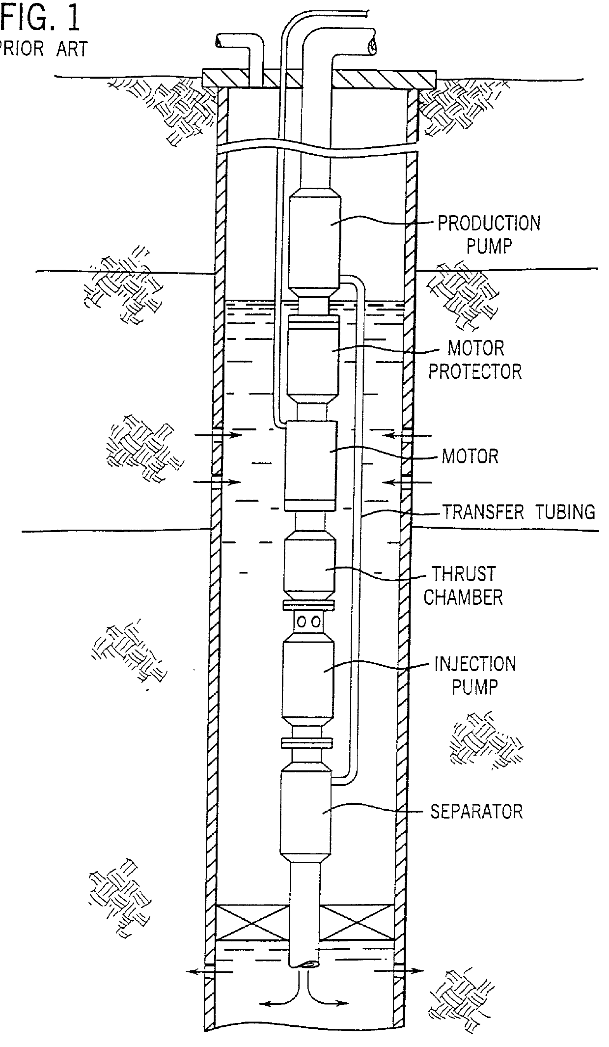
Turning now to the drawings, and referring first to FIG. 1, a pumping system is illustrated for separating wellbore fluids in accordance with certain heretofore known techniques. Specifically, the pumping system includes a production pump, a motor, an injection pump and a fluid separator. A motor protector is positioned intermediate the production pump and the motor. The motor is configured for driving both the production pump and the injection pump via internal power transmission shafts. The separator is positioned below the injection pump to receive flow from the injection pump. In operation, fluids enter the wellbore adjacent to the pumping system and are drawn into the injection pump. Fluids are then forced through the separator where production fluids are separated from non-production fluids, typically water. Production fluids are then transferred via transfer tubing to the production pump, while non-production fluids are injected into a discharge zone isolated by a set of pack...


PUM

PropertyMeasurementUnit
lengthsaaaaaaaaaa
torqueaaaaaaaaaa
mechanical poweraaaaaaaaaa

Abstract

A fluid separation system is provided for separating wellbore fluids into production fluids and non-production fluids. The system includes a separator adapted for transmitting mechanical power between a drive motor and at least one pump. The separator includes one or more separation units, such as hydrocyclone separators. A drive train traversing the separator is interfaced with drive elements, such as a submergible electric motor, and driven elements such as an injection or production pump. Wellbore fluids are channeled through the separator in either a push-through or pull-through manner. Production fluids are then transferred from the separator to the production pump for removal from the well. Non-production fluids are transmitted from the separator either to the injection pump for reinjection into a subterranean discharge zone, or directly into the discharge zone from the separator. The drive train elements traversing the separator are supported by antifriction bearings in interface plates on either end of the separator. The ability to transmit mechanical power through the separator facilitates assembly of pumping system components in various configurations as well as piping fluid communication paths between the pumping system components.

Description

1. Field of the InventionThis invention relates generally to the field of petroleum production and fluid separation. In particular, the invention relates to a novel technique for driving components of a submergible pumping system including an oil / water separator for separating production fluids from non-production fluids in a wellbore.2. Description of the Related ArtVarious techniques have been devised for raising production fluids from petroleum wells. In general, where a well has sufficient pressure to raise fluids without assistance, the well may be exploited directly by the control of above-ground valving and other equipment. In many wells, however, production fluids must be raised to the earth's surface by artificial means, such as submergible pumping units. Known submergible pumping systems typically include a submergible electric motor coupled to a submergible pump. The electric motor is coupled to power supply and control circuitry at the earth's surface, and is energized t...

Claims


Application Information

Patent Timeline
Patent Type & Authority Patents(United States)
IPC IPC(8): B01D17/02E21B43/34E21B43/12E21B43/38
CPCB01D17/0217E21B43/121E21B43/128E21B43/385
Inventor LEE, LAWRENCEMANN, JAY S.
Owner CAMCO INT
Why Eureka
Try Eureka