Estimator having a feedback loop

a feedback loop and estimation technology, applied in the field of data transmission, can solve the problems of increasing consumption power and inability to employ pipeline processing

Inactive Publication Date: 2000-03-07
NEC CORP
View PDF6 Cites 39 Cited by
  • Summary
  • Abstract
  • Description
  • Claims
  • Application Information

AI Technical Summary

Problems solved by technology

However, since the signal estimator uses estimated data one symbol before for calculation of the subsequent symbol, the pipeline processing cannot be employed.
Therefore, to achiev

Method used


Image

  • Estimator having a feedback loop
  • Estimator having a feedback loop
  • Estimator having a feedback loop

Examples


Embodiment Construction

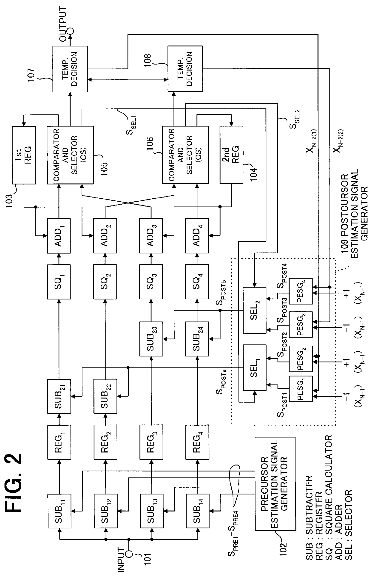
Referring to FIG. 2, there is shown a signal estimator according to an embodiment of the present invention. In general, transmission data has K values (K is an integer) and a transmission channel exhibits an impulse response including a precursor component for N symbols, a.sub.0 -a.sub.N-1, a center component for one symbol, a.sub.N, and a postcursor component for M symbols, a.sub.N+1 -a.sub.N+1, where N and M are an integer.

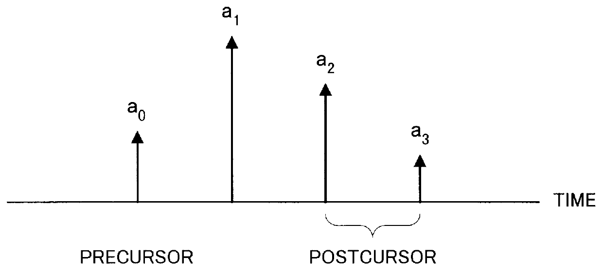
In this embodiment, assume K=2, M=2 and N=1 for simplicity. More specifically, the transmission data has two values: +1 and -1, and the transmission channel exhibits an impulse response including a precursor component of a.sub.0, a center component of a.sub.1, and a postcursor component of a.sub.2 and a.sub.3, as shown in FIG. 3.

In FIG. 2, input data which may be subjected to distortion due to ISI channel is received at an input terminal 101 and is supplied in common to four subtracters SUB.sub.11 -SUB.sub.14. The respective subtracters SUB.sub.11 -SUB.sub.14 su...


PUM


Abstract

A signal estimation loop includes a postcursor estimator which generates all possible postcursor estimation signals in a first past symbol period which is one symbol earlier based on a past estimated signal in a second past symbol period which is at least two symbols earlier. One of the possible postcursor estimation signals is selected based on the estimated signal to output a postcursor estimation signal to a subtracter in the symbol period. The subtracter subtracts the postcursor estimation signal from an input signal to produce a difference signal which is used to generate the estimated signal.

Description

1. Field of the InventionThe present invention generally relates to data transmission, and in particular to signal estimation in the presence of distortion such as intersymbol interference (ISI).2. Description of the Related ArtThere has been proposed Delayed decision-feedback sequence estimation (DDFSE), which is a method of estimating the distorted signals, in "Delayed Decision Feedback Sequence Estimation" by A. Duel-Hallen and C. Heegard (IEEE Transactions on communications, pp 428-436, Vol. 37, No. 5, May 1989). DDFSE is an estimation algorithm that would reduce computational complexity with only slight degradation in the quality of signal estimation compared with MLSE (maximum-likelihood sequence estimation) in digital communications over intersymbol interference channels.As another method for estimating the distorted signals, the inventor has proposed an adaptive reduced-state sequence estimation in NEC Research & Development (pp 188-194, Vol. 35, No. 2, April 1994). the adap...

Claims


Application Information

Patent Timeline
IPC IPC(8): H04L25/03H04L25/08H03M13/23H04B3/06
CPCH04L25/03324
Inventor MATUI, HITOSI
Owner NEC CORP
Why Eureka
Try Eureka