Selectable control energy and water conservation system

a technology of selectable control and energy conservation, applied in the direction of domestic hot water supply system, lighting and heating apparatus, heating types, etc., can solve the problems of system failure to address the problem of energy loss hot water energy loss problem,

Inactive Publication Date: 2000-03-21
HOULIHAN JOHN A
View PDF18 Cites 44 Cited by
  • Summary
  • Abstract
  • Description
  • Claims
  • Application Information

AI Technical Summary

Problems solved by technology

This system fails to address the problem of lost energy due to hot water cooling in the plumbing lines between hot water usage cycles.
He does not address the energy loss problem of hot water left to cool in the lines.
It does not address the problem of energy loss due to hot water cooling in the lines.
He does not address the energy loss problem of hot water left to cool in the lines.
This system cannot be utilized effectively with a conventional water heater.
He does not address the energy loss problem of hot water left to cool in the lines.
This system does not address the problem of lost energy due to hot water cooling in the plumbing lines, between hot water usage cycles.
He does not address the energy loss...

Method used


Image

  • Selectable control energy and water conservation system
  • Selectable control energy and water conservation system
  • Selectable control energy and water conservation system

Examples


Embodiment Construction

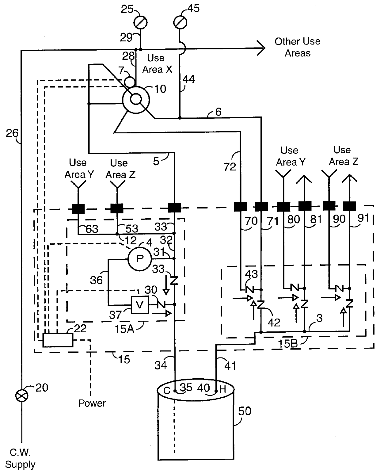
Referring now to FIG. 1.

The selectable control energy and water conservation system is configured as a unit, for use in a structure whose conduits have been specifically and economically routed to interface correctly with the system's flow control components. It may be wall mounted or free standing. Its most energy efficient location would be in close proximity to the structure's hot water supply. However, it can be located at a more convenient space in the structure without altering its operation or manufacture.

A water saver segment 15A of a flow control unit 15 is configured to function with each use area in the structure, where a hot water outlet is located. Use area X is supplied hot water through a hot water distribution conduit 6 which may be placed in fluid communication, through a selectable flow control valve 10, with a cold water inlet conduit 5, branched from a cold water manifold 12. The flow path is opened or closed, by selectable flow control valve 10. This permits the...


PUM


Abstract

The system is unique in that a structure's plumbing lines are effectively routed, to stop energy and water waste, while adding little to construction cost. Water pressure to hot water supply (50) is controlled through a selectable flow control valve (10). A hot water manifold (3) and check valves 42 and 43 produce a dual line connection, between hot water manifold (3) and the hot water use area. In the water saver mode, positioning selectable flow control valve (10) causes pump (4) to draw water from distribution conduit (6), through selectable flow control valve (10), through cold water manifold (12) and solenoid valve (37) to hot water supply (50). Pump (4) causes hot water to fill distribution conduit (6), to the hot water use area. This circulation delivers hot water to replace water standing in the line. Circulation period is determined by controller (22). When selectable flow control valve (10) is positioned to the use mode, supply pressure at cold water conduit (28) is applied through selectable flow control valve (10), then via cold water manifold (12), to hot water supply (50). Positioning selectable flow control valve (10) to the energy saver mode causes, cold water pressure to be interrupted to hot water supply (50) and directed through feedback conduit (72) and conduit (71), to a junction down stream from hot water manifold (3). Supply pressure forces hot water towards open hot water outlet (45), thus all hot water delivered from hot water manifold (3) is utilized.

Description

BACKGROUND FIELD OF THE INVENTIONThis invention relates to a hot and cold water delivery system, more particularly to a water saving, energy conserving system that is sufficiently flexible in design, to be conveniently installed in a variety of residential or commercial structures.DESCRIPTION OF THE PROBLEM AREAIn a conventional plumbing system, which includes a water heating tank, it is a well known fact that, after every use, hot water is retained in the line between the hot water supply and the outlet, and it cools. Later this cooled water is wasted down the drain, waiting for hot water to arrive at the outlet; water and the energy to heat that water are wasted. In order to solve the singular problem of water waste, hot water recirculating systems are suggested, but unfortunately, no energy is saved.Hot water recirculation systems require additional piping to complete a loop from the furthest hot water outlet, returning to the hot water supply. In structures where hot water use a...

Claims


Application Information

Patent Timeline
IPC IPC(8): E03C1/00F24D17/00
CPCE03B7/04E03B7/045F24D17/00Y02A20/411Y10T137/6497Y10T137/86397
Inventor HOULIHAN, JOHN A.
Owner HOULIHAN JOHN A
Why Eureka
Try Eureka