Cooling device boiling and condensing refrigerant

Inactive Publication Date: 2000-03-21
DENSO CORP
View PDF12 Cites 79 Cited by
  • Summary
  • Abstract
  • Description
  • Claims
  • Application Information

AI Technical Summary

Problems solved by technology

Therefore, the size of the cooling device becomes large.
However, in this case, velocity distribution of the heat pipe 200 in the longitudinal direction becomes uniform, thereby decreasing the cooling effect of the cooling

Method used


Image

  • Cooling device boiling and condensing refrigerant
  • Cooling device boiling and condensing refrigerant
  • Cooling device boiling and condensing refrigerant

Examples


first embodiment

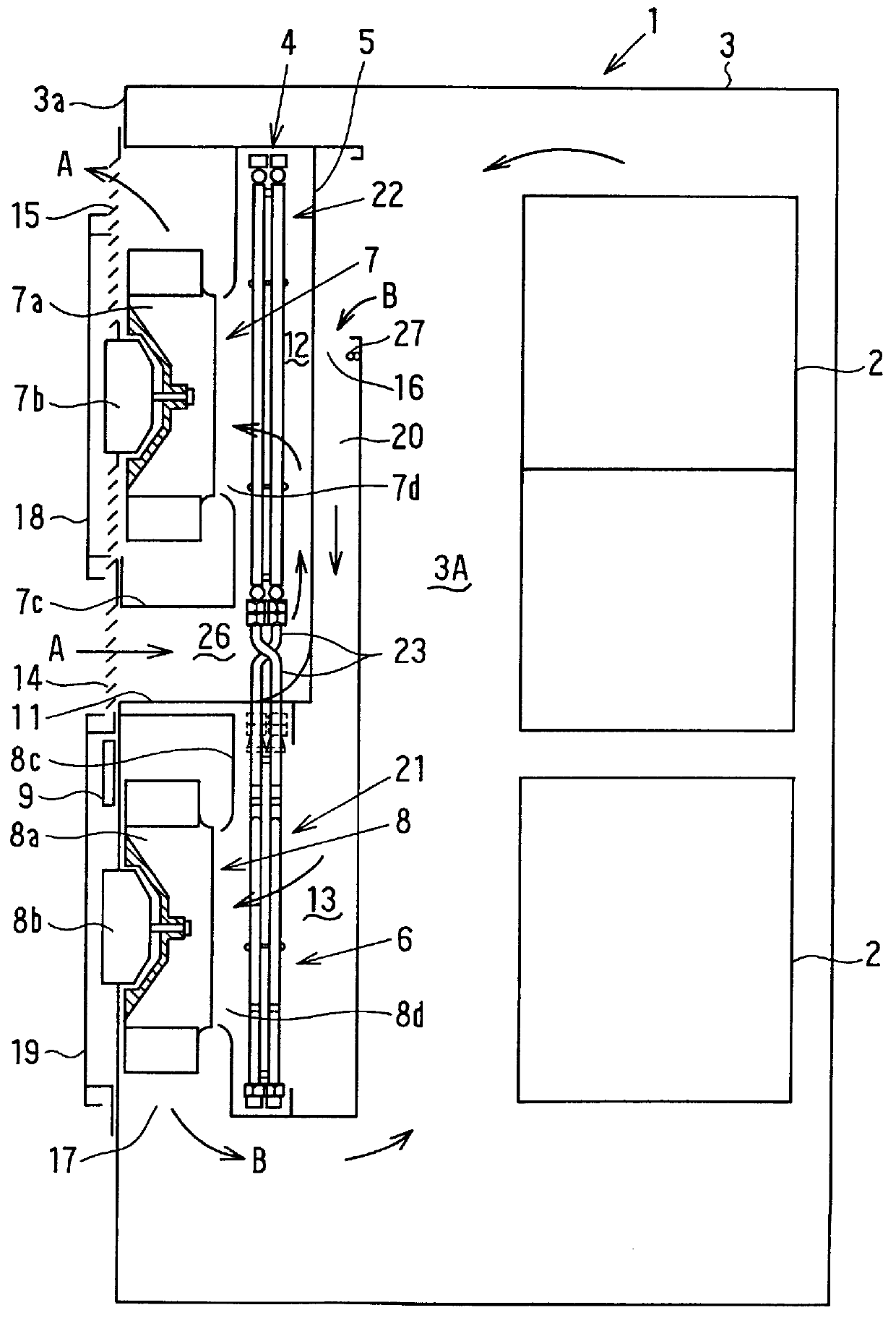
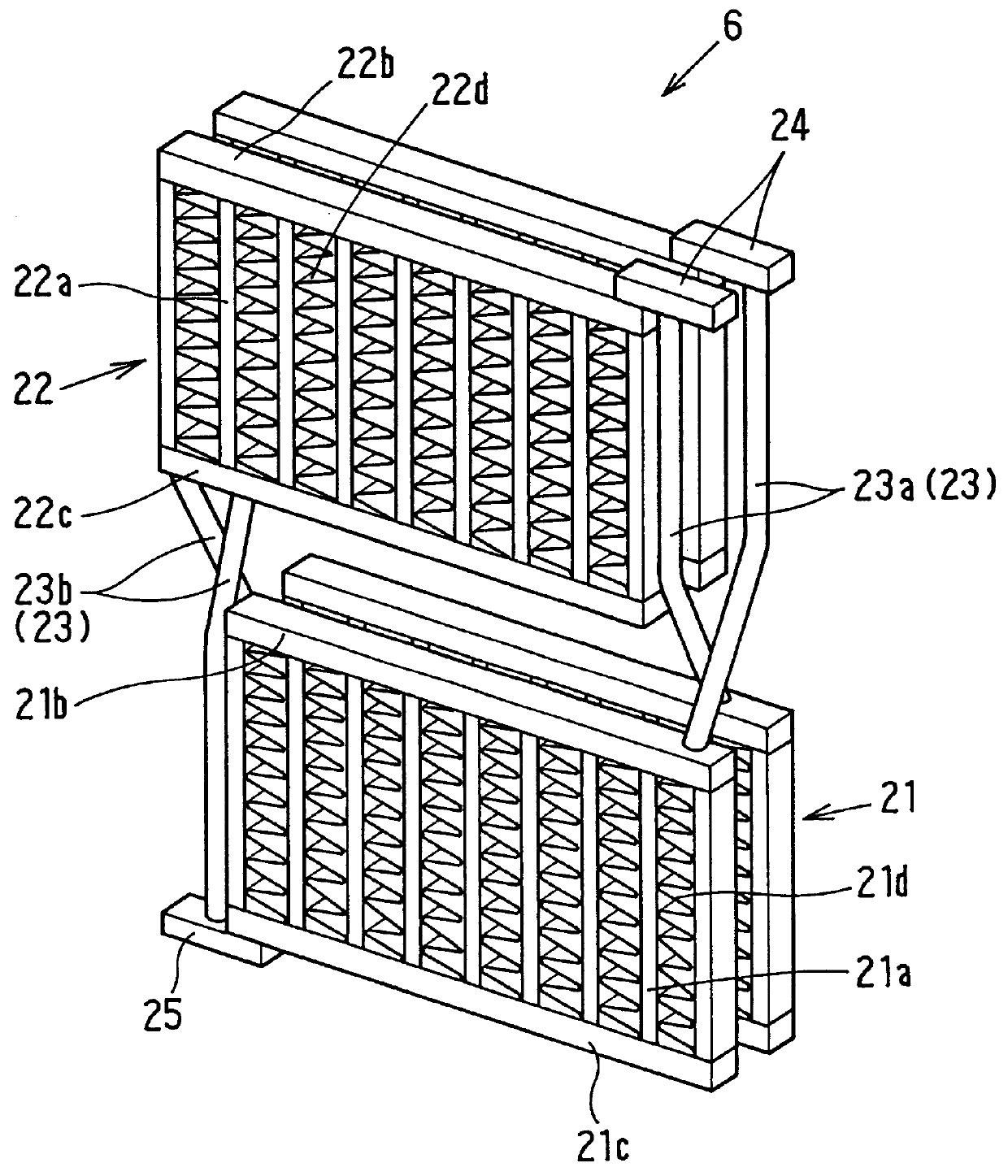
The boiling unit 6 includes a heat receiving portion 21 disposed approximately vertically in the high-temperature-side heat transmission space 13, a heat-radiating portion 22 disposed approximately vertically in the low-temperature-side heat transmission space 12, and a connection pipe 23 for connecting the heat receiving portion 21 and the heat radiating portion 22. A predetermined amount of refrigerant is sealed within the boiling unit 6 through a tube. As the refrigerant, CH.sub.2 FCF.sub.3 or water may be used. A liquid refrigerant is sealed within the boiling unit 6 at a level approximately corresponding to the partition plate 11 when the boiling unit 6 is not operated. In the first embodiment, the panel cooler 4 includes two boiling units 6. Because both boiling units 6 have the same structure, only one boiling unit 6 is described.

As shown in FIG. 3, the heat receiving portion 21 includes a plurality of heat receiving pipes 21 a disposed in parallel, upper and lower tanks 21b ...

second embodiment

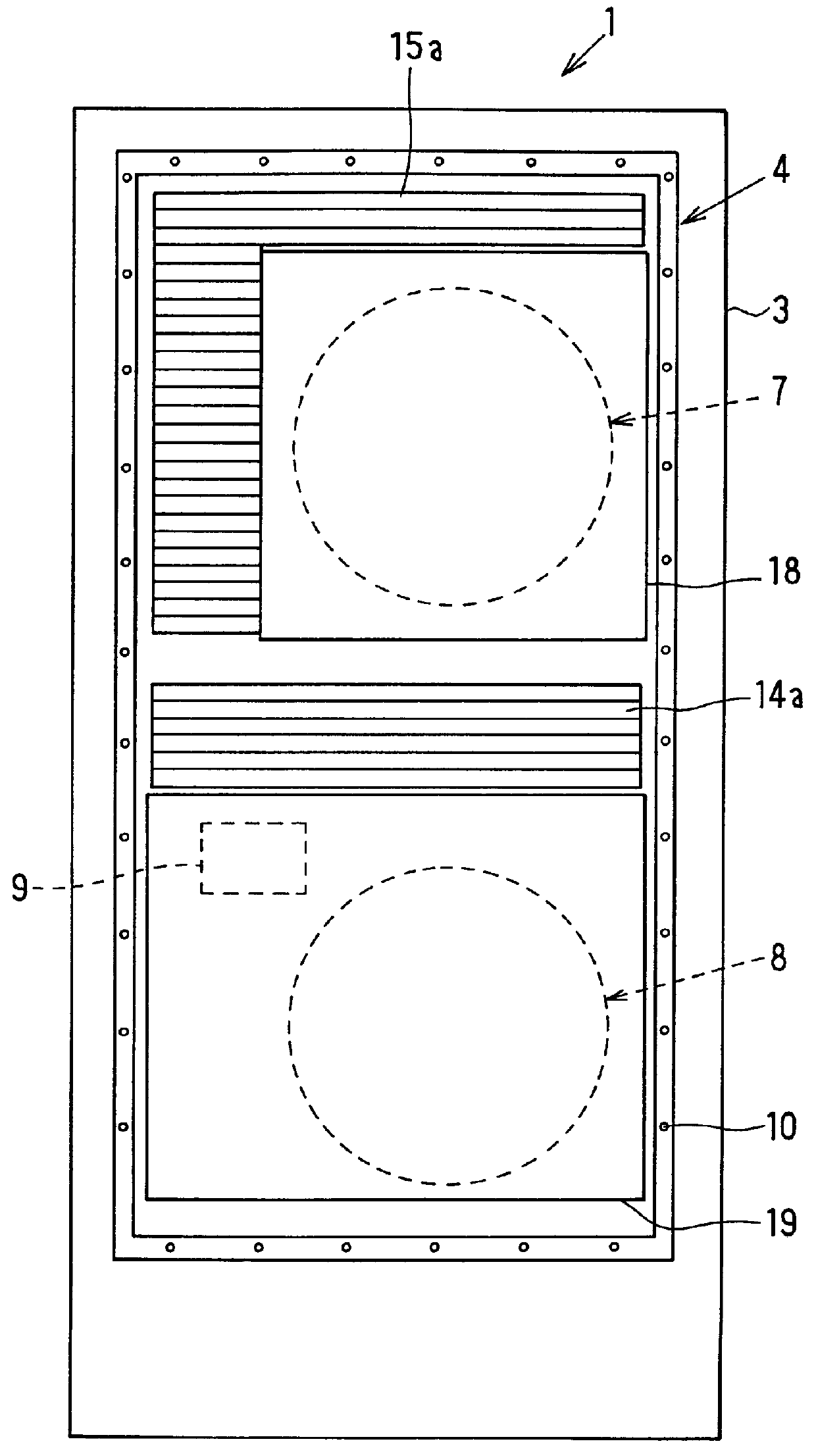
In the second embodiment, a panel cooler 4 has a supporting shaft (not shown) at one end side, and the panel cooler 4 is attached to the housing 3 such that it can rotate around the supporting shaft, as shown in FIG. 4. Further, the upper and lower side blower units 7 and 8 are disposed at the inner side (i.e., the right side in FIG. 4) of the boiling unit 6. In this case, the pipe space of the connection pipe 23 is provided on the lower side of the partition plate 11, and an air passage 28 through which inside air of the housing 3 flows can be provided using the pipe space of the connection pipe 23.

Further, relative to the housing 3, the whole panel cooler 4 is rotatable around the supporting shaft. Therefore, the maintenance and change for the upper and lower side blower units 7 and 8 can be readily performed. In this case, main parts such as the electric motors 7b and 8b can be provided inside the panel cooler 4. In the second embodiment, a hinge 29 is provided on the rear surfac...

fifth embodiment

As shown in FIG. 8, in the fifth embodiment, the air passage 26 or the air passage 28 between the first and second connection pipes 23a and 23b is provided with a duct 30. Therefore, heat transmission between air flowing through the duct 30 and refrigerant flowing through the connection pipe 23 can be interrupted. When outside air flows through the duct 30, gas refrigerant flowing through the first connection pipe 23a is not condensed by the outside air in the duct 30. Further, when inside air of the housing 3 flows through the duct 30, condensed liquid refrigerant flowing through the second connection pipe 23b is not evaporated by the inside air in the duct 30.

In each of the above-described embodiments, both boiling units 6 are used. However, as shown in FIG. 9, a single boiling unit 6 may be used.

A sixth preferred embodiment of the present invention will be described with reference to FIGS. 10 through 14B.

A box-shaped cooling device 100 can be applied to a radio base station devic...


PUM


Abstract

A cooling device includes: a partition plate for partitioning an interior of a case into a first fluid passage through which first fluid having a high temperature flows and a second fluid passage through which second fluid having a low temperature flows; a heat receiving portion disposed in the first fluid passage; a heat radiating portion disposed in the second fluid passage; and a connection pipe for communicating the heat receiving portion and the heat radiating portion. The heat radiating portion is disposed at an upper side of the heat receiving portion in such a manner that the second fluid from a front side of the heat radiating portion flows into a rear side of the heat radiating portion through a pipe space between the heat radiating portion and the heat receiving portion, and further passes through the heat radiating portion from the rear side toward the front side of the heat radiating portion. Thus, the cooling device has a small size while improving the cooling capacity of the cooling device.

Description

1. Field of the InventionThe present invention relates to a cooling device for cooling an interior of a sealed housing for accommodating a heat-generating member such as an electronic part.2. Description of Related ArtConventionally, a heat-generating member such as an electronic part is used while being located in a sealed housing. Because outside air cannot be circulated inside the housing for ventilation in this case, a heat exchange between air inside the housing and air outside the housing is performed to cool the heat-generating member.For example, in a cooling device described in JP-B2-2-3320, a heat pipe is disposed along a side wall surface of a housing. Heat exchange between air inside the housing and air outside the housing is performed through the heat pipe. That is, as shown in FIG. 15, a lower portion 210 of the heat pipe 200 is disposed within the housing having a high temperature, and an upper portion 220 of the heat pipe 200 is disposed outside the housing. However,...

Claims


Application Information

Patent Timeline
IPC IPC(8): F28D15/02H05K7/20
CPCF28D15/0266F28F1/126H05K7/206F28F2215/04
Inventor KAWAGUCHI, KIYOSHIKADOTA, SHIGERUKISHITA, KOUJI
Owner DENSO CORP
Why Eureka
Try Eureka