One piece fuel cell separator plate

a fuel cell and separator plate technology, applied in the direction of cell components, cell components, fused electrolyte fuel cells, etc., can solve the problems of close tolerances and very difficult engineering problems

Inactive Publication Date: 2000-03-21
INST OF GAS TECH
View PDF14 Cites 78 Cited by
  • Summary
  • Abstract
  • Description
  • Claims
  • Application Information

AI Technical Summary

Problems solved by technology

Due to the thermal gradients between cell assembly and cell operating conditions, differential thermal expansions, and the ne

Method used


Image

  • One piece fuel cell separator plate
  • One piece fuel cell separator plate
  • One piece fuel cell separator plate

Examples


Embodiment Construction

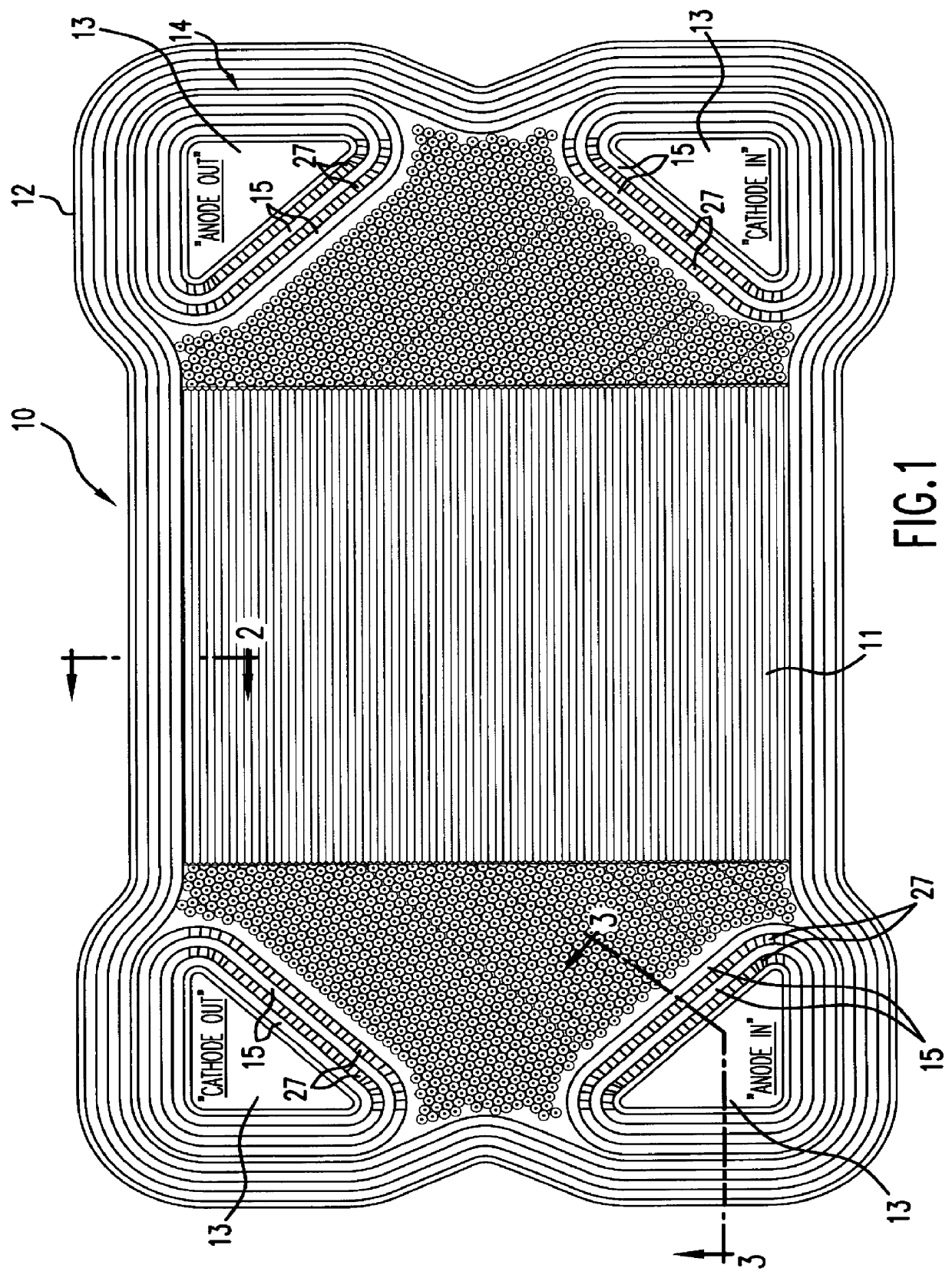
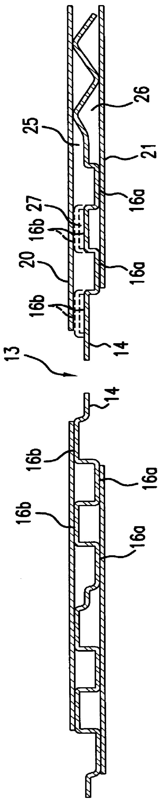
A one-piece separator plate 10 for an internally manifolded fuel cell in accordance with one embodiment of this invention is shown in FIG. 1. Separator plate 10 comprises a centrally disposed active region 11 and peripheral seal region 12 which extends completely around the periphery of separator plate 10. Separator plate 10 forms at least one pair of perforations 13 substantially geometrically disposed on opposite sides of active region 11. In this way, a reactant gas passing through one of said perforations passes through active region 11 and out through the perforation 13 on the opposite side of active region 11.

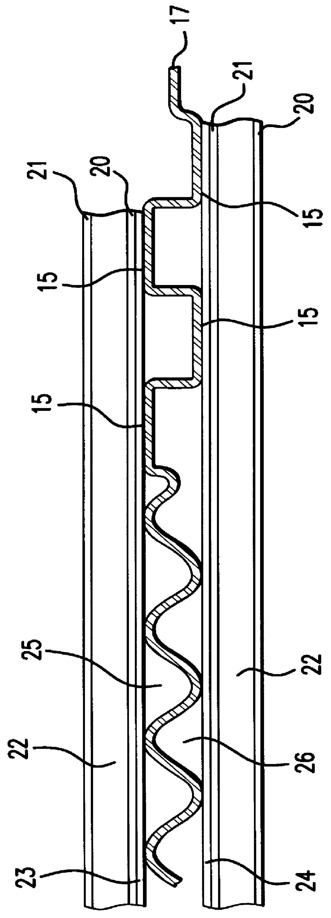
Peripheral seal region 12 comprises peripheral seal structure 17 on each face of separator plate 10 completely around the periphery of each said face of separator plate 10, peripheral seal structure 17 comprising flattened peripheral seal structures 15, as shown in FIG. 2, for sealing against adjacent fuel cell components facing each face of separator plate 10.

Each perfor...


PUM


Abstract

A separator plate for an internally manifolded fuel cell stack comprising a centrally disposed active region, a peripheral seal region, and forming at least one pair of perforations substantially geometrically disposed on opposite sides of the centrally disposed active region. The peripheral seal region comprises a peripheral seal structure on each face of the separator plate completely around the periphery of each said face. A manifold seal region in each face completely encloses each perforations, the manifold seal region comprising conduits on one of said faces for communication of a gas between the centrally disposed active region and at least the one pair of perforations. The separator plate is comprised of one sheet of a material suitable for use as a separator plate, preferably a pressed sheet metal.

Description

1. Field of the InventionThis invention relates to a separator plate for a fuel cell stack, preferably an internally manifolded molten carbonate fuel cell stack. This invention also relates to subassemblies of an anode / current collector / separator plate / current collector / cathode therefore which upon assembly provide effective sealing between said fuel cell components. The subassemblies provide ease of assembly resulting in reduced labor costs and long-term stability while the separator plate design simplifies the design of the interacting fuel cell components, reduces the assembly time in constructing a fuel cell stack, improves sealing by using a rigid and increased sealing area, prevents electrode creeping, eliminates the "cookie cutter" effect, and eliminates the internal resistance within each cell.Generally, fuel cell electrical output units are comprised of a stacked plurality of individual cells separated by inert or bi-polar electronically conductive ferrous metal separator p...

Claims


Application Information

Patent Timeline
IPC IPC(8): H01M8/02H01M8/14
CPCH01M8/0206H01M8/0247H01M8/0254H01M8/0258H01M2008/147H01M2300/0051Y02E60/50Y02E60/526H01M8/244H01M8/2483H01M8/026H01M8/0271
Inventor REEDER, KENNETH W.
Owner INST OF GAS TECH
Why Eureka
Try Eureka