Method and apparatus handling radioactive waste material

a technology of radioactive waste and containment technique, applied in separation processes, liquid fuel feeders, gravity filters, etc., can solve the problems of inconvenient containment technique described above, inconvenient in many respects, and far too expensive techniques

Inactive Publication Date: 2000-03-21
VATTENFALL
View PDF5 Cites 21 Cited by
  • Summary
  • Abstract
  • Description
  • Claims
  • Application Information

AI Technical Summary

Benefits of technology

A specific object of the invention is, therefore, to provide a method and an apparatus achieving inexpensive and effective dewatering of void water from such waste before this is contained with a view to ultimate disposal, the storage of such void water being thus avoided.
Another specific object of the invention is to provide a method and an apparatus enabling a reduction of the total cost of the containment of the waste and involving effective utilisation of the volume of the compartments in which the waste is to be ultimately disposed of.
A particular object of the invention thus is to reduce the total volume of waste, including the container structure, that is to be ultimately disposed of.

Problems solved by technology

Low-level waste from nuclear power plants occurs, inter alia, in the form of contaminated ion-exchange material obtained when cleaning the aqueous phase of the secondary side of leaking steam generators.
However, the containment technique described above is inconvenient in many respects.
First, this technique is far too expensive.
Second, this technique means that the deposition compartment in which the chill moulds are to be placed is poorly utilised as to volume.
Accordingly, this prior-art technique is anything but cost-effective.
A further inconvenience of the prior-art technique is that the ion-exchange material will, owing to its content of various chemical additives serving to improve the ion-exchange function, exhibit an unfavourable pH value rendering the embedment procedure more complicated.
The technique taught in GB-A-2,216,034 is disadvantageous not only in that the container structure is highly complicated and, hence, expensive, but also in that the water removed by centrifugal action may well have an unacceptably high activity, necessitating further processing of the water.

Method used


Image

  • Method and apparatus handling radioactive waste material
  • Method and apparatus handling radioactive waste material
  • Method and apparatus handling radioactive waste material

Examples


Embodiment Construction

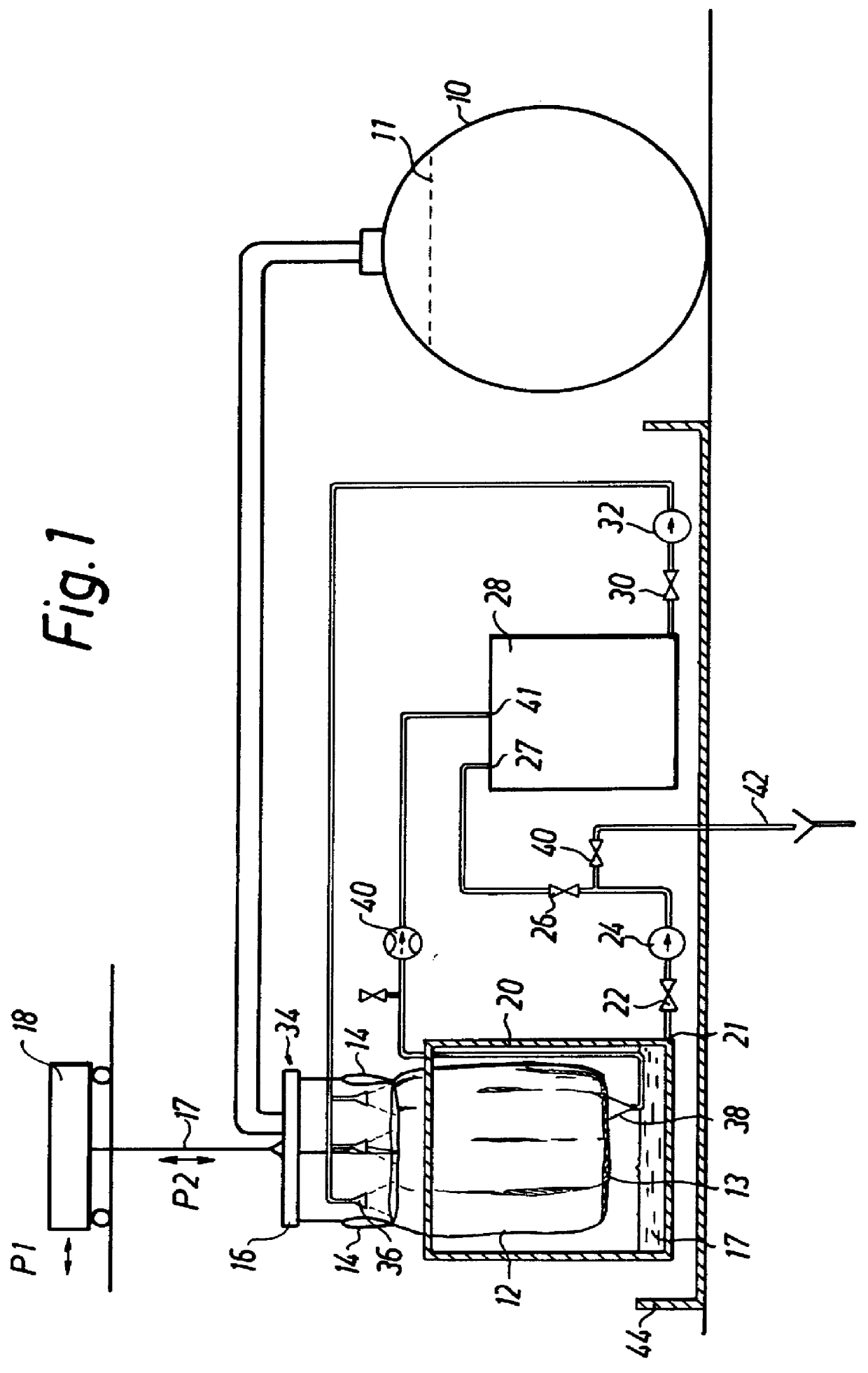
FIG. 1, to which reference is now made, illustrates an embodiment of an apparatus according to the invention for dewatering and containing low-level or intermediate-level waste, which for exemplifying purposes is here assumed to consist of spent ion-exchange material as above. Thus, the ion-exchange material may originate from an ion-exchange filter for cleaning the aqueous phase at the secondary side of steam generators in nuclear power plants. The material may have an activity in the order of 5,000-300,000 Bq / kg, thus exceeding the limit value for direct deposition, consequently, the material is dewatered, contained and tested as to its contents of nuclides before being deposited, preferably in the ground.

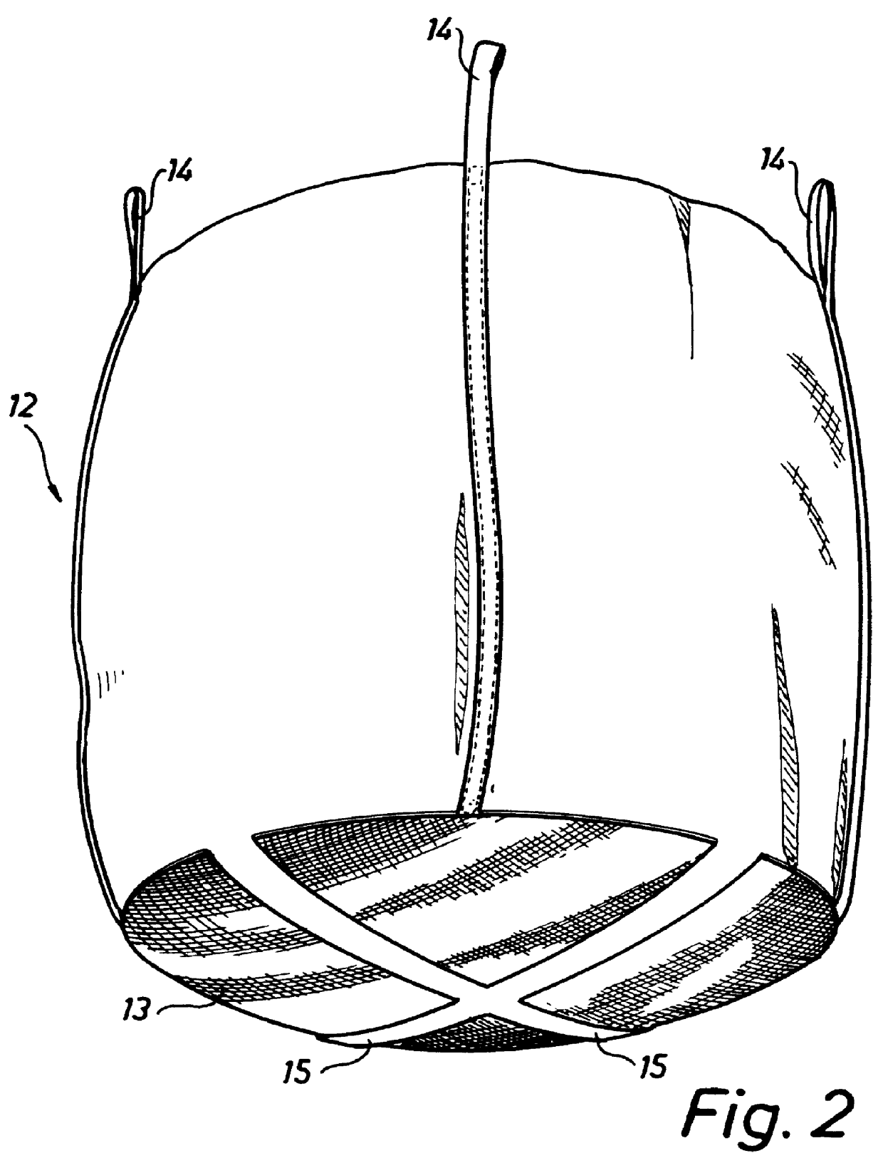
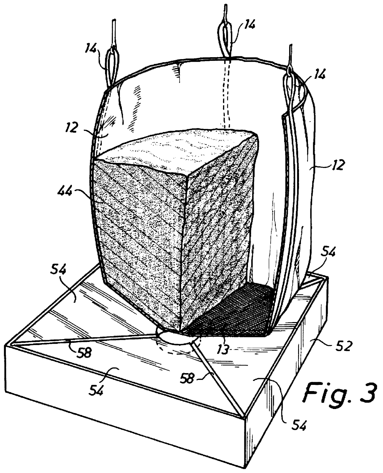
The apparatus shown in FIG. 1 comprises a storage tank 10, a bigbag-type inner sack 12 provided with a straining-cloth bottom 13 and being, with the aid of four lifting eyes 14, suspended from a lifting yoke 16, which in turn is suspended from a travelling (P1) trolley 18 via 17....


PUM

PropertyMeasurementUnit
volumeaaaaaaaaaa
volumeaaaaaaaaaa
timeaaaaaaaaaa

Abstract

PCT No. PCT / SE96 / 00306 Sec. 371 Date Sep. 30, 1997 Sec. 102(e) Date Sep. 30, 1997 PCT Filed Mar. 7, 1996 PCT Pub. No. WO96 / 28828 PCT Pub. Date Sep. 19, 1996In a method and an apparatus for dewatering and containing radioactive, aqueous waste (44), the latter is introduced into a filtration container (12) and is ultimately disposed of in a disposable container structure (12, 48, 50), which comprises the filtration container (12) holding the dewatered waste (44), as well as an outer container (50) enclosing the filtration container (12). The filtration container is an inner sack (12) having a bottom (13) which is provided with a straining cloth and through which essentially all the dewatering is carried out. After the dewatering operation has been completed, the inner sack (12) is sealed and placed in the outer container (50) in order to be ultimately disposed of. For purposes of cleaning, the filtration water (17) may be recirculated through the waste during the dewatering operation.

Description

The present invention generally relates to the handling and disposal of radioactive waste, in particular low-level and intermediate-level waste, from nuclear power plants.To be more specific, the invention concerns a method for dawatering and containing aqueous, low-level or intermediate-level waste, as well as an apparatus for implementing this method.DESCRIPTION OF THE PRIOR ARTLow-level waste from nuclear power plants occurs, inter alia, in the form of contaminated ion-exchange material obtained when cleaning the aqueous phase of the secondary side of leaking steam generators. Such cleaning may be performed in what is commonly referred to as ion-exchange beds containing a suitable amount of ion-exchange material, for instance in the order of 2000 kg per bed. As the ion-exchange material is spent and replaced with fresh material, the spent, low-level and aqueous ion-exchange material has to be taken care of in some suitable fashion. The activity of this material may be in the orde...

Claims


Application Information

Patent Timeline
Patent Type & Authority Patents(United States)
IPC IPC(8): G21F9/04G21F9/06G21F9/30
CPCG21F9/04G21F9/06Y10S588/90
Inventor SJOWALL, SONY
Owner VATTENFALL
Why Eureka
Try Eureka