Ram driving device and press machine using same

a driving device and ram technology, applied in the direction of presses, presses, manufacturing tools, etc., can solve the problems of increasing the maintenance cost of the hydraulic cylinder and the hydraulic circuit arrangement, the inability to apply the same ram driving device to various press machines of different moving strokes and speeds, and the inability to use the same ram driving device to press machines which require a large press power, etc., to achieve the effect of increasing the maintenance cost of the press power and the increase of the press

Inactive Publication Date: 2000-03-28
AMADA MFG AMERICA
View PDF12 Cites 23 Cited by
  • Summary
  • Abstract
  • Description
  • Claims
  • Application Information

AI Technical Summary

Benefits of technology

to provide a ram driving device which can generate a large press power of various moving strokes and various moving speeds freely by a minimum possible modification thereof, without increasing the maintenance cost thereof.
In the ram driving device according to the present invention, the movement stroke and the vertical speed of the ram can be controlled freely by changing the rotational speed of a plurality of servomotors in synchronism with each other. In addition, the press power can be increased by use of an appropriate number of servomotors driven in synchronism with each other. As a result, it is possible to adopt the ram driving device according to the present invention to the press machines of various type of different ram movement strokes and ram vertical speeds.

Problems solved by technology

In the above-mentioned conventional ram driving devices, however, there exist the following problems:
In the first example, since the ram is moved up and down by the hydraulic source, the cost required for the maintenance of the hydraulic cylinder and the hydraulic circuit arrangement is relatively high.
In the second example, although the maintenance cost is not high, since the moving stroke and the speed of the ram cannot be controlled freely, it is impossible to apply the same ram driving device to various press machines of different moving strokes and speeds.
Further, in the third example, since the drive axle is rotated by the servomotor, although the moving stroke and the speed of the ram can be changed freely, since the press power of the ram is relatively small, there exists a problem in that the servomotor cannot be used for a press machine which requires a large press power.

Method used


Image

  • Ram driving device and press machine using same
  • Ram driving device and press machine using same
  • Ram driving device and press machine using same

Examples


first embodiment

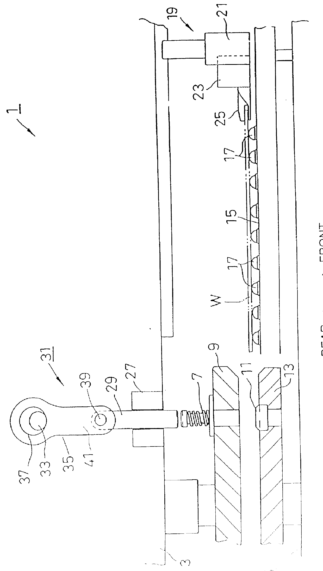
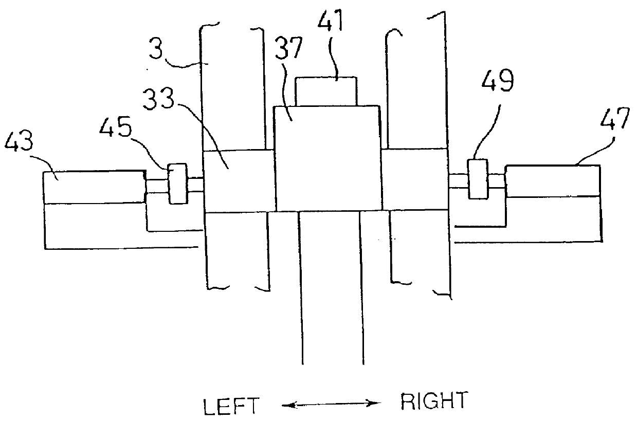
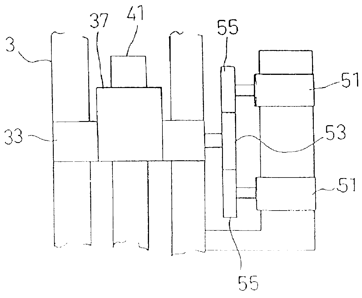
FIG. 1 shows the ram driving device according to the present invention. In the drawing, a punch press is shown as an example of a press machine. The punch press is provided with an upper frame 3 and a lower frame 5 both being opposed to each other in the vertical direction. To the upper frame 3, an upper turret 9 is rotatably attached. On the upper turret 9, a plurality of punches 7 (only one is shown in FIG. 1) are arranged. On the lower frame 5, a lower turret 13 is also rotatably mounted. On the lower turret 13, a plurality of dies 11 (only one is shown in FIG. 1) are also arranged in such a way that each pair of the punch 7 and the die 11 are mated with each other.

On the front side (the right side in FIG. 1) of the lower turret 13 of the lower frame 5, a table 15 for supporting a plate workpiece W is provided. The table 15 is provided with a number of free bearings 17 for rotatably supporting the workpiece W thereon. Further, on the front side of the upper turret 9 of the upper ...

second embodiment

FIGS. 4 and 5 show the present invention. In this embodiment, the motion converting mechanism 63 of the ram driving device 57 is composed of a ball screw member 61 rotatably provided on the upper frame 3 via two bearings 59 (as the horizontal drive axle 33); a nut member 77 in mesh with the ball screw member 61; a first (upper) pivotal link 73; and a second (lower) pivotal link 67. The upper end of the first pivotal link 73 is pivotally linked with the upper frame 3 of the press machine via a link pin 71 and the lower end thereof is pivotally linked with a recessed guide hole 75 formed in the nut member 77 via another link pin 69, so as to be movable in the right and left direction in FIG. 4 or 5 when the ball screw member 61 is moved. The upper end of the second pivotal link 67 is pivotally linked with the first pivotal link 73 via the link pin 69 engaged with the recessed guide hole 75 of the nut member 77 and the lower end thereof is pivotally linked with the ram 29 via another l...

third embodiment

FIGS. 6 and 7 show the present invention. In this embodiment, the ram driving device 81 is provided with a motion converting mechanism 83 which comprises an eccentric ring cam 85 formed integral with the horizontal drive axle 33 and formed with inner and outer circular guide surfaces 85 and 87, and a cam follower 91 rotatably attached to the ram 29 and moved up and down along an annular space formed between the two inner and outer circular guide surfaces 87 and 89 of the eccentric ring cam 85.

The operation of the above-mentioned embodiments will be described herein below.

Under the condition that the plate-shaped workpiece W is clamped by the clamping device 25, when the first carriage 21 is moved in the front and rear direction and when the second carriage 23 is moved in the right and left direction, the workpiece W can be located in position between the upper turret 9 and the lower turret 13. Further, a pair of the predetermined punch 7 and the die 11 is indexed at just under the r...


PUM

PropertyMeasurementUnit
pressureaaaaaaaaaa
thickaaaaaaaaaa
thicknessaaaaaaaaaa

Abstract

A ram driving device for a press machine having: a ram; a horizontal drive axle (33) rotatably provided horizontally in a frame (3) of the press machine; a motion converting mechanism (35, 63, 83) associated with the horizontal drive axle, for converting a rotational motion of the horizontal drive axle into up-and-down motion of the ram (29); and a plurality of servomotors (43, 47) linked with the horizontal drive axle, for rotating the horizontal drive axle in synchronism with each other, to drive the ram up and down. The motion converting mechanism is a connecting rod (35); and a link mechanism (63) driven by a ball screw (61) and a nut member (77); and an eccentric ring cam (33) and a cam follower (91). Since the ram can be driven by a plurality of the servomotors synchronously, the device can generate a large press power of various moving stroke and various moving speed freely, without increasing the maintenance cost thereof.

Description

1. Field of the InventionThe present invention relates to a ram driving device for moving a ram up and down, which is suitable for a machine such as a press machine, bending machine, etc.2. Description of the Related ArtSome examples of the conventional ram driving device for moving a ram up and down in a press machine such as a punch press machine will be first described herein below.As a first ram driving device, there exists such a device that a hydraulic cylinder having a piston linked with a ram is actuated by a hydraulic circuit arrangement.As a second ram driving device, there exists such a device that a horizontal drive axle is rotatably provided in a frame of a press machine; a rotational motion of the drive axle is converted into the ram up-and-down motion by a motion converting mechanism; and a drive motor is linked with the drive axle via a clutch brake to rotate the drive axle. Here, the motion converting mechanism is usually composed of an eccentric portion attached to...

Claims


Application Information

Patent Timeline
Patent Type & Authority Patents(United States)
IPC IPC(8): B30B1/00B30B1/10B30B1/26B30B15/14B30B15/06
CPCB30B1/103B30B15/14B30B1/266Y10T74/19056Y10T83/8726
Inventor SETO, YOSHIHARUHIROSE, SHUNZO
Owner AMADA MFG AMERICA
Why Eureka
Try Eureka