Multi-configured lighting fixture for surface mounting

Inactive Publication Date: 2000-03-28
KENALL MFG
View PDF5 Cites 57 Cited by
  • Summary
  • Abstract
  • Description
  • Claims
  • Application Information

AI Technical Summary

Problems solved by technology

Additionally, the "depth" of the lens itself may vary wit

Method used


Image

  • Multi-configured lighting fixture for surface mounting
  • Multi-configured lighting fixture for surface mounting
  • Multi-configured lighting fixture for surface mounting

Examples


Embodiment Construction

The aims and objects of the present invention are accomplished, in part, by providing in a lighting fixture, a family of structural components which may be used in various combinations, selectively, to provide a group of differing fixture structures or "designs", each adapted to meet and satisfy different practical applications and uses.

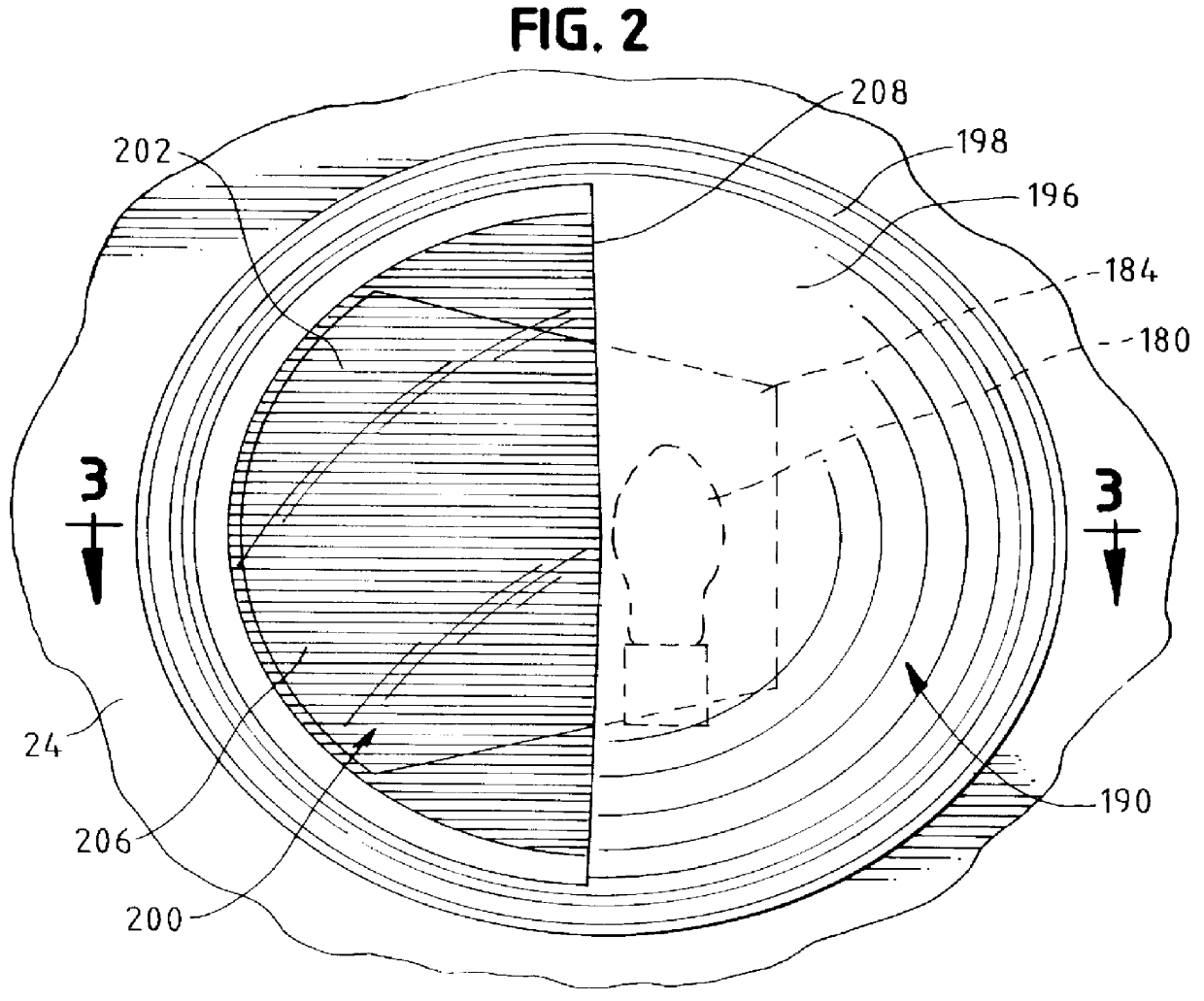
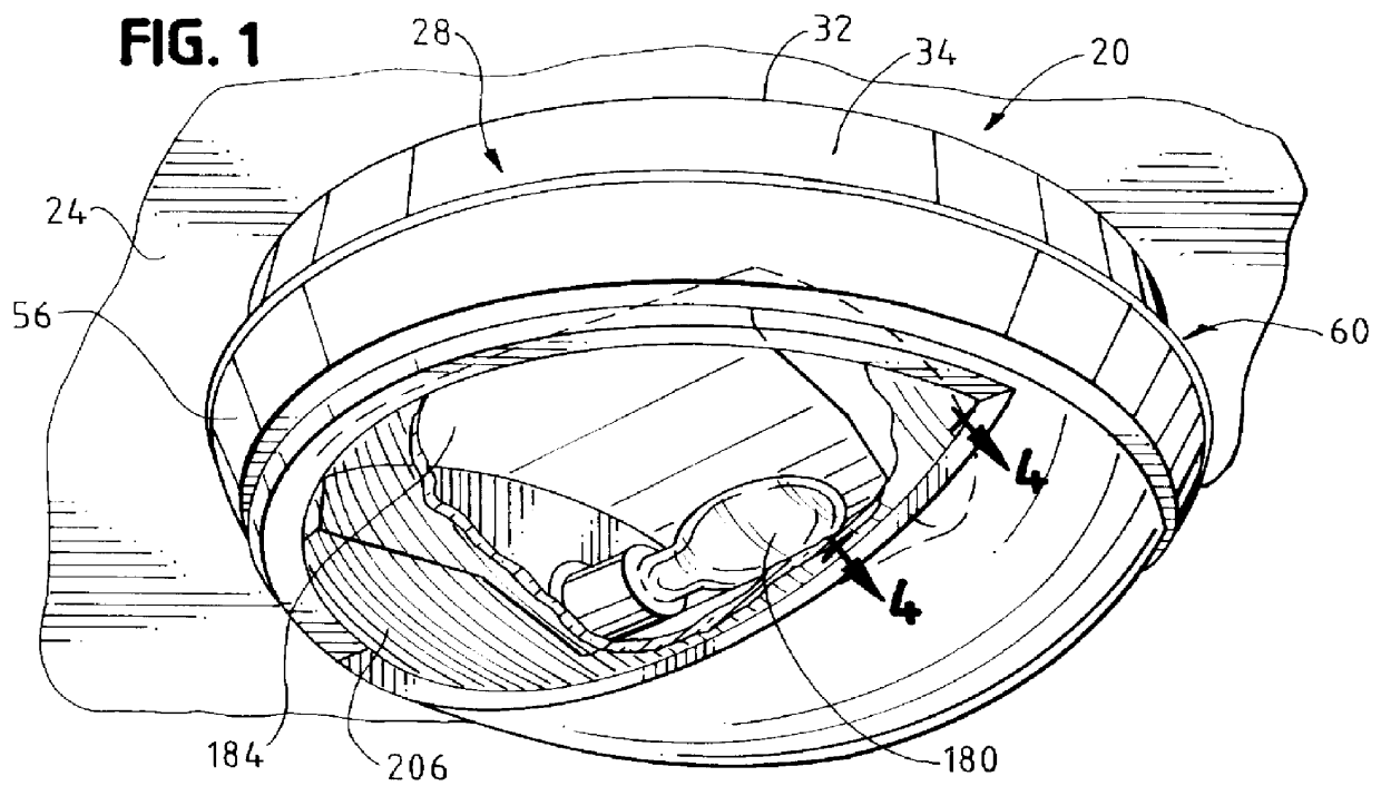
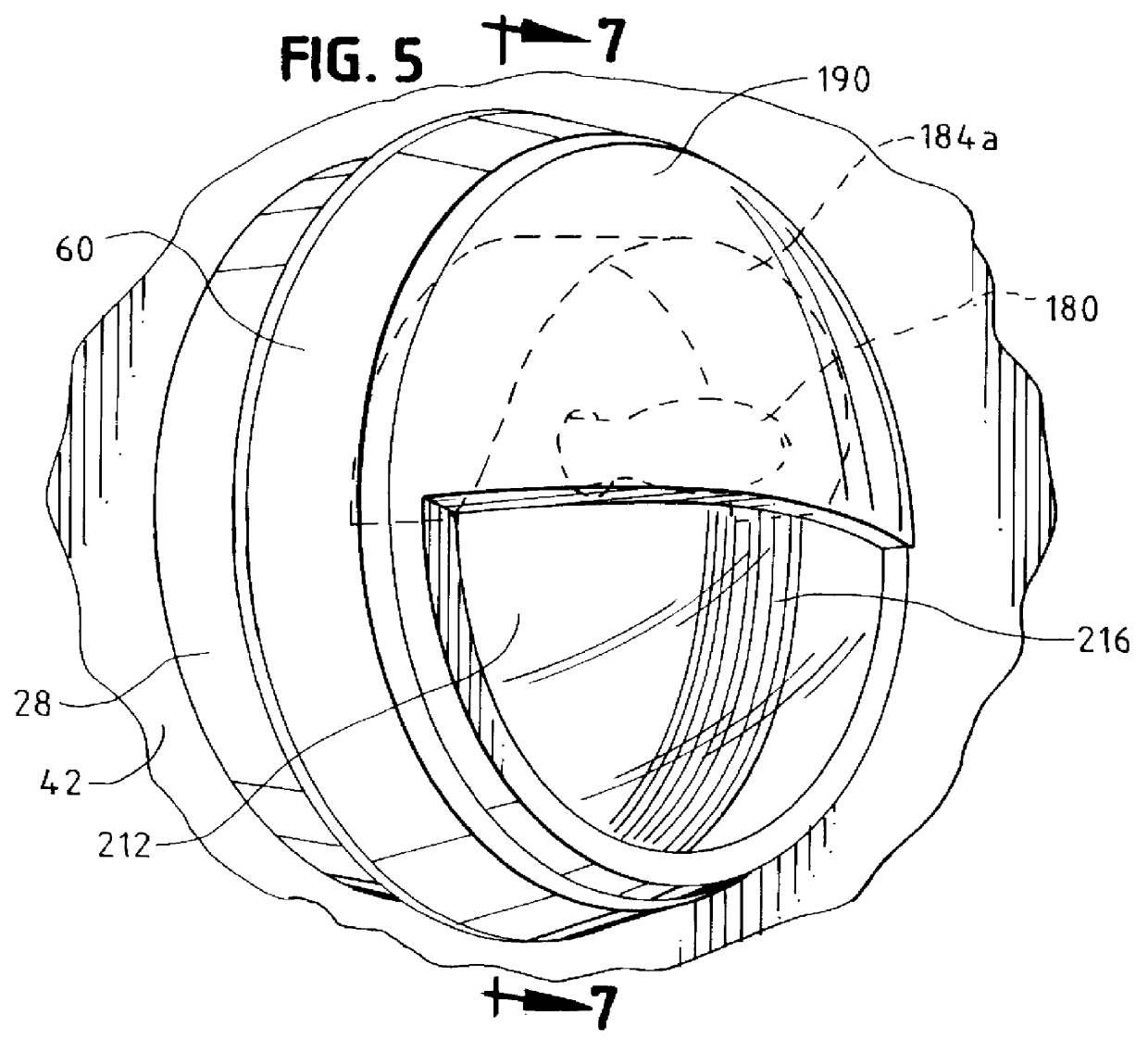
The multi-configurational, multi-functional electrical lighting fixture of the invention, which is especially engineered and constructed for high abuse areas and applications, is conveniently adapted for surface mounting, as on walls or ceilings. The fixture includes a lens of U.V. stabilized, high-impact-resistant, injection-molded polycarbonate plastics, integrally formed with two selective, separate and distinct, high-performance reflector / refractor surface systems carried by a single lens, as separate zonal areas. The first system generates a long and relatively narrow throw or light distribution pattern, and the second system, a short and wide t...


PUM


Abstract

There is described a multi-configurational, multi-functional electrical lighting fixture for high-abuse application and structured for surface mounting. The fixture includes a lens of U.V. stabilized, high impact-resistant, injection molded polycarbonate plastics, integrally formed with two selective, separate and distinct, high-performance reflector/refractor surface systems carried by the single lens, as separate zonal areas. The first system generates a long and narrow "throw", and the second system a short and wide "throw". A molded, opaque "eyelid" provides optimum lamp shielding and controls light distribution. The lens surmounts a lens base to which it is secured by means of unique internal, integrally-molded lugs received in cooperating hook-shaped slots. An 0-ring gasket establishes a water-tight seal. Unlocking of the assembly is deterred by means of a single, tamper-resistant screw. The lens base is mounted on a deep casting, with or without an interposed cast aluminum baseplate. Alternatively, the lens base may be mounted directly on the cast aluminum baseplate, without the deep casting, to provide a low-profile fixture structure.

Description

FIELD AND BACKGROUND OF THE INVENTIONThe present invention relates to an electrical lighting fixture. More particularly, the invention is directed to a multi-configured electrical fixture for high-abuse lighting, and adapted for surface mounting.The fixture of the invention is especially useful in applications where one desires to be able to exercise options, for example, to install a fixture housing having a low profile, or, alternatively, to provide a deeper housing when higher energy input is desired so as to provide increased illumination.In accordance with the practice of the present invention, one is enabled quickly and easily to modify or to "adapt" the fixture by incorporating an auxiliary fixture component. The latter constitutes a substantially larger housing in the form of a relatively deep, dish-like metal casting. The addition of the deeper, energy-dissipating housing is effected without the need to remove the original baseplate which constitutes the floor-like base or ...

Claims


Application Information

Patent Timeline
IPC IPC(8): F21V3/00F21V3/04F21V5/00F21V5/02F21V17/14F21V13/12F21V17/00F21V13/00F21V15/00F21S8/00F21V11/16F21Y101/00
CPCF21S8/033F21S8/04F21V3/04F21V5/02F21V15/01F21V13/12F21V17/14F21V31/005F21V11/16F21Y2101/00F21Y2115/10
Inventor MCCARTHY, CHARLES A.PASKO, GABRIEL
Owner KENALL MFG
Why Eureka
Try Eureka