Method of making an acoustic probe

a technology of acoustic probe and acoustic field, which is applied in the field of acoustic transducers, can solve the problems of increasing the complexity of the interconnection of all the transducers, the limitations of manufacturing cost and acoustic "transparency", and the electronics of the transducers

Inactive Publication Date: 2000-04-04
THOMSON CSF SA
View PDF1 Cites 28 Cited by
  • Summary
  • Abstract
  • Description
  • Claims
  • Application Information

AI Technical Summary

Problems solved by technology

The presence of this intermediate element makes the interconnection of all the transducers even more complicated.
This interconnection problem is one of the main problems currently encountered in the manufacture of acoustic imaging probes.
However, when a two-dimensional matrix of transducers is envisaged, it is necessary to produce a surface-type system for connecting the elements, this being complicated by the presence of the acoustically absorbent layer.
Nevertheless, the interconnection of a

Method used


Image

  • Method of making an acoustic probe
  • Method of making an acoustic probe
  • Method of making an acoustic probe

Examples


Embodiment Construction

In general, the acoustic probe according to the invention comprises a transducer consisting of a matrix (a linear or preferably two-dimensional matrix) of piezoelectric sensors, the said transducer being mounted on a matrix of facing interconnection contacts. This interconnection matrix consists of the ends of metal tracks emerging from one of the faces of an interconnection system described hereinbelow and called a "backing". The opposite ends of the metal tracks are connected to an electronic control and analysis device.

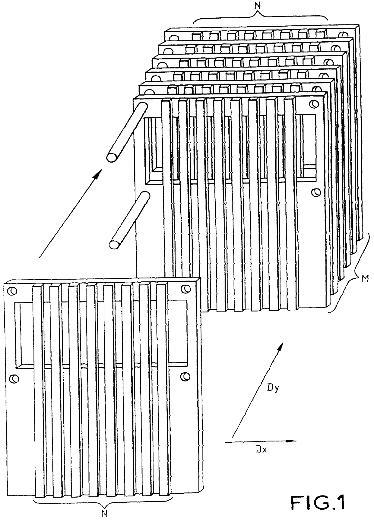
In the case of a matrix of M.times.N piezoelectric elements, the interconnection system may be produced in the following manner:

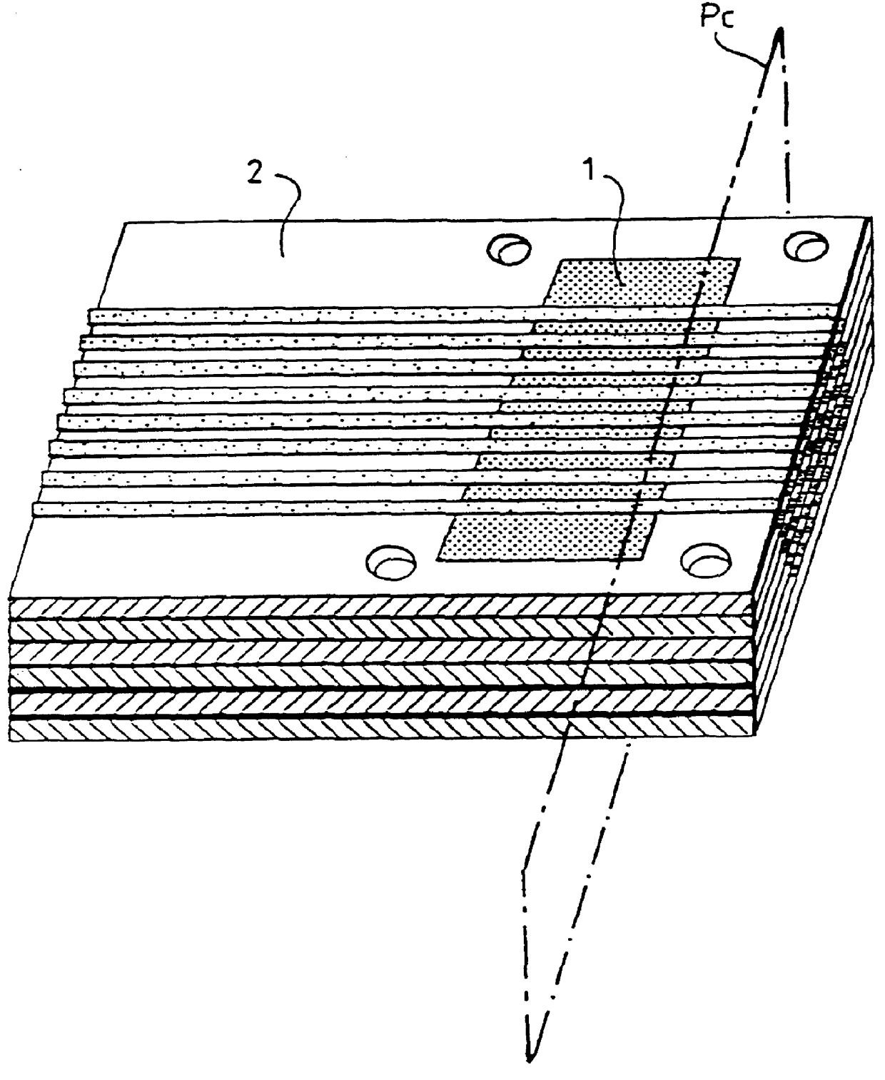
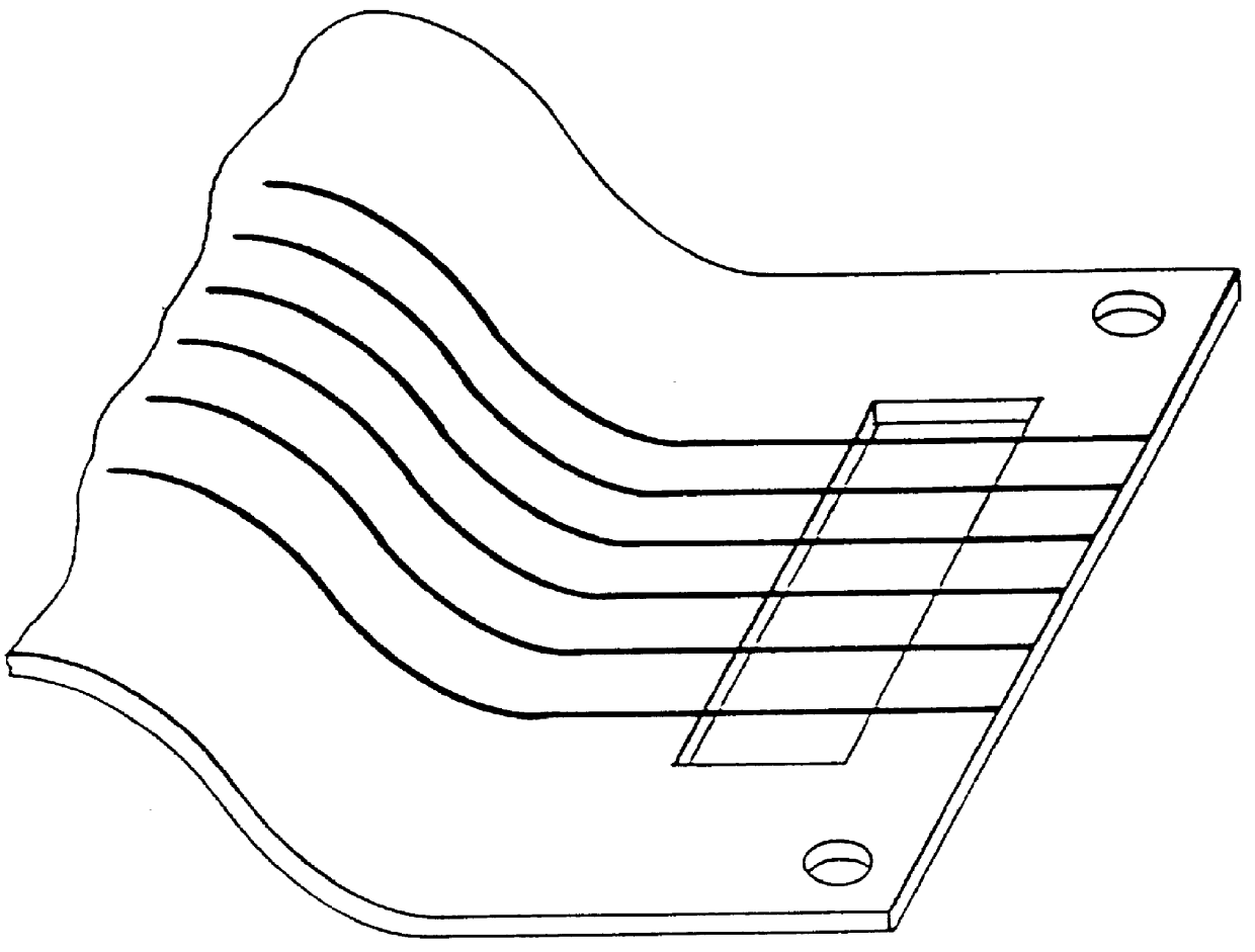
According to one variant of the invention, M dielectric substrates are used, on which N conducting tracks have been produced along one axis D.sub.x. Each substrate includes a window in which the conducting tracks are locally left bare. The set of M substrates is aligned and stacked in a direction D.sub.y, as illustrated in FIG. 1. A stack ...


PUM

PropertyMeasurementUnit
Thicknessaaaaaaaaaa
Dielectric polarization enthalpyaaaaaaaaaa
Flexibilityaaaaaaaaaa

Abstract

PCT No. PCT/FR96/01650 Sec. 371 Date Jul. 2, 1997 Sec. 102(e) Date Jul. 2, 1997 PCT Filed Oct. 22, 1996 PCT Pub. No. WO97/17145 PCT Pub. Date May 15, 1997An acoustic probe and a method for making the same. The probe includes a novel interconnection network consisting of two portions, i.e., a first portion in which MxN conductive paths have a section contacting MxN piezoelectric transducers and are arranged at a pitch (PN) in a direction (Dx) and at a pitch (PM) in direction (Dy) within the acoustic absorption material; and a second portion in which the MxN conductive paths are arranged on M dielectric substrates spaced apart at a pitch (P'M) and each provided with N paths are arranged at a pitch (P'N). A method for making the acoustic probe is also disclosed. The dielectric substrates may advantageously be flexible printed circuits optionally including chips.

Description

The field of the invention is that of acoustic transducers which can be used in particular in medical or underwater imaging.DISCUSSION OF THE BACKGROUNDIn general, an acoustic probe comprises a set of piezoelectric transducers connected to an electronic control device via an interconnection system. These piezoelectric transducers emit acoustic waves which, after reflection off a given medium, deliver information relating to the said medium. Acoustic waves emitted not towards the external medium to be analysed, but in the opposite direction, disturb the response of the medium and make it essential to interpose, between the piezoelectric transducers and the electronic device, a medium which absorbs the acoustic waves. The presence of this intermediate element makes the interconnection of all the transducers even more complicated.This interconnection problem is one of the main problems currently encountered in the manufacture of acoustic imaging probes. This is because the miniaturizat...

Claims


Application Information

Patent Timeline
IPC IPC(8): B06B1/06A61B8/00G01N29/24H01L41/09
CPCB06B1/0629Y10T29/49158Y10T29/42B06B1/06
Inventor BUREAU, JEAN-MARCBERNARD, FRAN.CEDILLA.OISCALISTI, SERGE
Owner THOMSON CSF SA
Why Eureka
Try Eureka