Chuck for capping machine

a technology of chuck and capping machine, which is applied in the direction of caps, rotating screw stopper insertion, application, etc., can solve the problems of increasing the time it takes to separate the chuck from the cap, premature jaw wear, and chuck jaw wear, so as to reduce the wear of the chuck jaw

Inactive Publication Date: 2000-04-04
PNEUMATIC SCALE CORP
View PDF13 Cites 41 Cited by
  • Summary
  • Abstract
  • Description
  • Claims
  • Application Information

AI Technical Summary

Benefits of technology

It is a further object of the present invention to provide a chuck for a capping machine which reduces wear of chuck jaws during repeated operation.

Problems solved by technology

Chucks have required a substantial amount of force to be transferred through many components.
The many components through which the force has to be transferred cause an increase in the time it takes to separate the chuck from the cap.
This slower separation causes slipping of the jaws on the cap contributing to premature jaw wear.
The magnitude of the force required also causes premature jaw wear.
Chucks made in accordance with the prior art are limited in the size of the caps they can apply, due to how wide the jaws can be opened for large caps, which require a larger jaw opening capability.
Some capping machines do not have sufficient vertical space available to allow the chucks made in accordance with the prior art to be raised high enough.

Method used


Image

  • Chuck for capping machine
  • Chuck for capping machine
  • Chuck for capping machine

Examples


Embodiment Construction

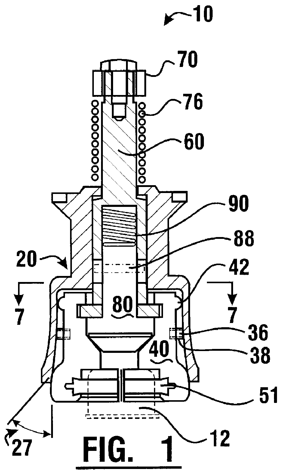
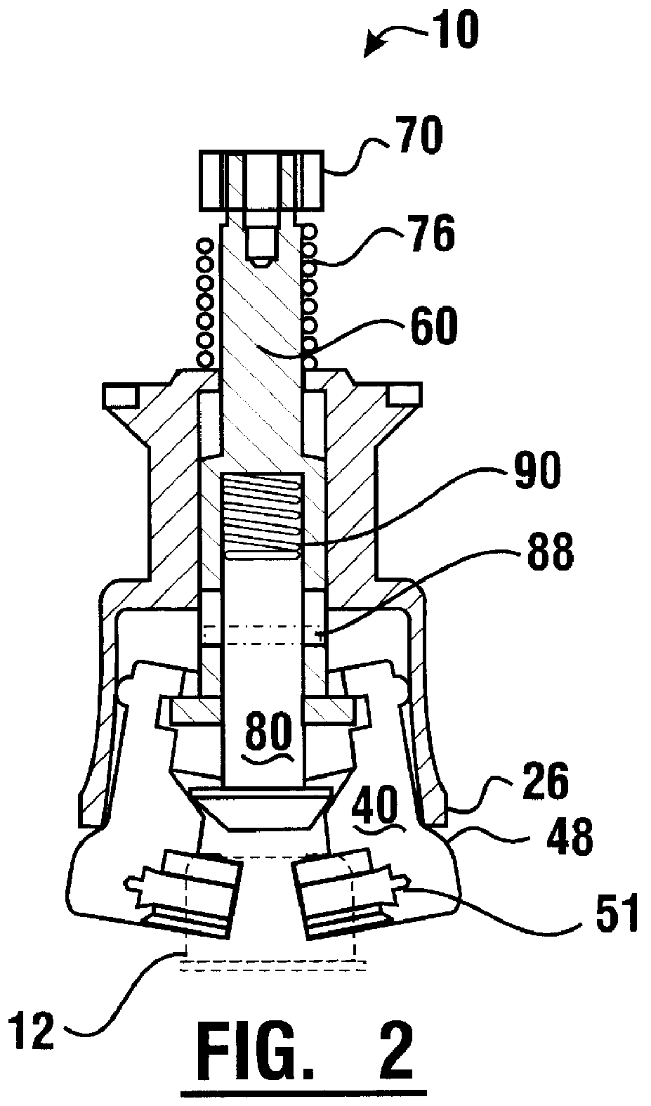
A preferred embodiment of a chuck 10 of the present invention is generally shown in FIGS. 1 and 2. Chuck 10 has a jaw bell 20, a plurality of jaws 40, a spindle or jaw stem 60 and a sleeve or stripper 80. In FIG. 1 chuck 10 is shown with jaw bell 20 in an extended position and jaws 40 in closed positions holding a cap 12 shown in phantom. In FIG. 2 chuck 10 is shown with jaw bell 20 in a retracted position and jaws 40 in open positions.

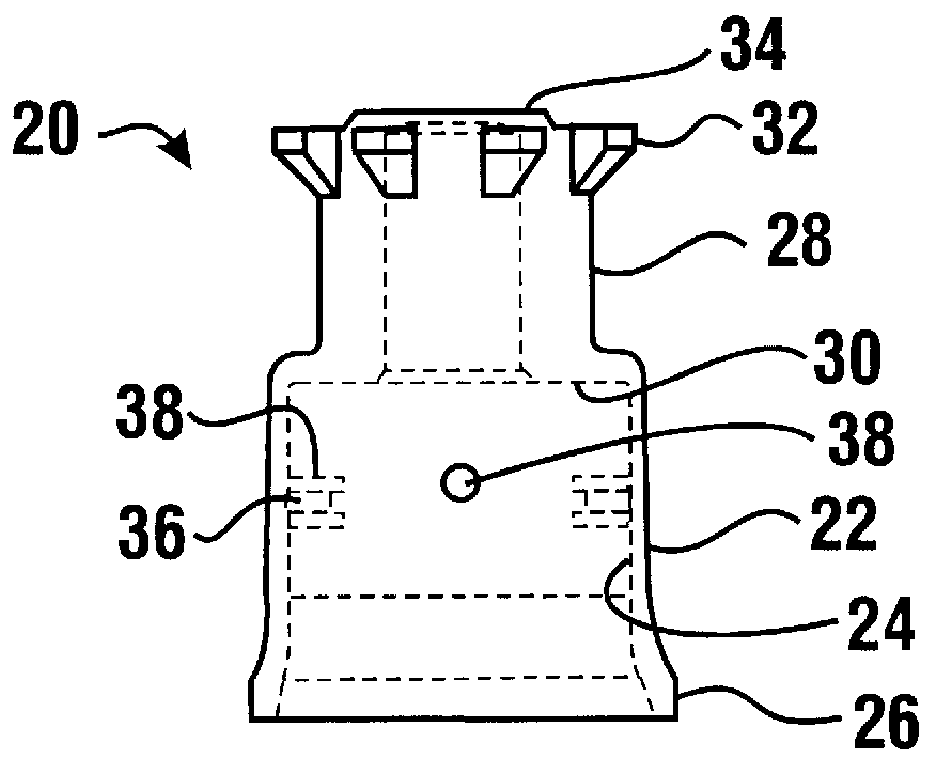
As shown in FIGS. 3 and 4, jaw bell 20 has a lower bell portion 22. Lower bell portion 22 has a wall 24 which is preferably flared outwardly slightly longitudinally and annular in cross-section. In this embodiment wall 24 flares outwardly beginning at approximately midway between its upper end and lower end at an angle 27 of approximately 6.9.degree. from the vertical. Further, at the flared end of wall 24 the thickness of wall 24 is increased to form a lip 26.

Lower bell portion 22 at least one post 36 extending radially inward from the inner surface ...


PUM


Abstract

A chuck (10) has a jaw bell (20), a lower bell portion (22) surrounding a plurality of jaws (40) and a hub (28) surrounding an upper portion of a jaw stem (60). A second portion of the jaw stem extends beyond a jaw bell hub (28) and is surrounded by a compressed jaw stem spring (76). The jaw stem spring is retained between a bell hub collar (34) and a jaw stem collar (70). The force of the jaw stem spring holds the jaw bell around the jaws, holding the jaws in a closed position. A stripper (80) has an upper end (82) carried within the jaw stem. A stripper spring (90) located above the upper end of the stripper is compressed and surrounded by the jaw stem. The lower end of the stripper has a disk (84) with a frusto-conical cross-section in slidable contact with the jaws. The jaw stem spring exerts more force downward on the jaw bell than the stripper spring exerts downward on the stripper to hold the jaw bell around the jaws and the jaws closed. Moving the jaw bell upward further compresses the jaw stem spring so that the force of the stripper spring moves the stripper downward, thereby moving the jaws downwardly and outwardly from the jaw bell to open the jaws.

Description

This invention relates to a chuck for a bottle capper, the chuck having jaws and a stripper, and more specifically to a chuck in which a stripper spring forces the stripper downward to open the jaws.There are a number of bottle capping machines currently used to apply screw caps onto bottles. In general such machines employ a reciprocating mechanism to reciprocate a screw cap applying spindle assembly through a capping cycle. A screw cap chuck, typically constructed of a tool grade steel, is attached to the spindle. These machines operate at a predetermined downward stroke while applying a pre-determined torque to the screw cap. The operating height of the chuck is usually adjustable to allow for various bottle heights.The primary elements of the screw-on capping chuck are chuck jaws, a jaw bell, a stripper, a spring and a stem. The jaws are retained in the bell by the stem as it is acted upon by the spring. An adaptor connects the chuck to a spindle sleeve and transmits the rotary ...

Claims


Application Information

Patent Timeline
Patent Type & Authority Patents(United States)
IPC IPC(8): B67B3/20B67B3/00
CPCB67B3/2066
Inventor HARPER, JASON E.MCSHERRY, SCOTT A.SOBODOSH, ANDREW J.
Owner PNEUMATIC SCALE CORP
Why Eureka
Try Eureka