Method of producing quartz glass bodies

a technology of quartz glass and glass body, which is applied in the direction of glass blowing apparatus, glass making apparatus, glass shaping apparatus, etc., can solve the problems of reducing usefulness, requiring a high cost of apparatus and controls, and non-homogeneous quartz glass body

Inactive Publication Date: 2000-04-11
HERAEUS QUARZGLAS
View PDF17 Cites 87 Cited by
  • Summary
  • Abstract
  • Description
  • Claims
  • Application Information

AI Technical Summary

Problems solved by technology

This creates areas of differing reactivity of the preform which make themselves known especially during subsequent chemical reactions in further treatment of the preform and which can result in non-homogeneousness of the quartz glass body after the sintering of the preform.
In addition, the complicated translational motion of the burner blocks in this known process requires a high expense related to the apparatus and the controls.
Such axial density gradient in the preform does not reduce the usefulness for many applications of quartz glass bodies subsequently produced from the preform

Method used


Image

  • Method of producing quartz glass bodies
  • Method of producing quartz glass bodies
  • Method of producing quartz glass bodies

Examples


example 2

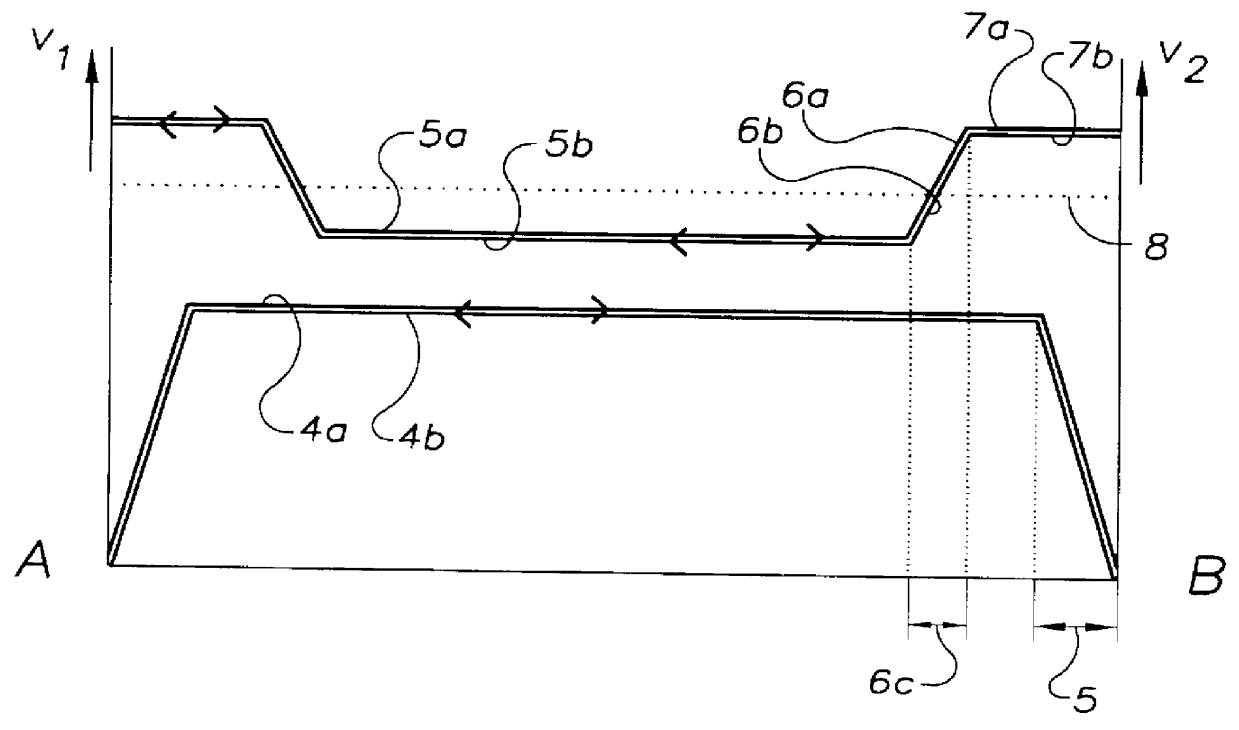
In FIG. 2. as well, the peripheral velocity of the preform is plotted on the y-axis as v.sub.1 and the translational velocity of the burner block as v.sub.2.

The average translational velocity of the burner block is 800 mm / min (curve 4a and 4b). Apart from the braking or accelerating distances 5 in the area of the turnaround points A and B which are insignificant as far as concerns the average translational velocity, the translational velocity is kept constant, both during the entire motion cycle and during the entire deposition process (in terms of the rate). The lengths of the braking or accelerating distances 5 are in the range of a few millimeters.

The preform peripheral velocity v.sub.1 is controlled by a fixed program. It is adjusted over a distance of about 9 cm between the turnaround points A and B at 12 m / min (curve sections 5a and 5b). During a forward motion of the burner block, for example toward the turnaround point B and from about 3 cm before it, the peripheral velocity...

example 3

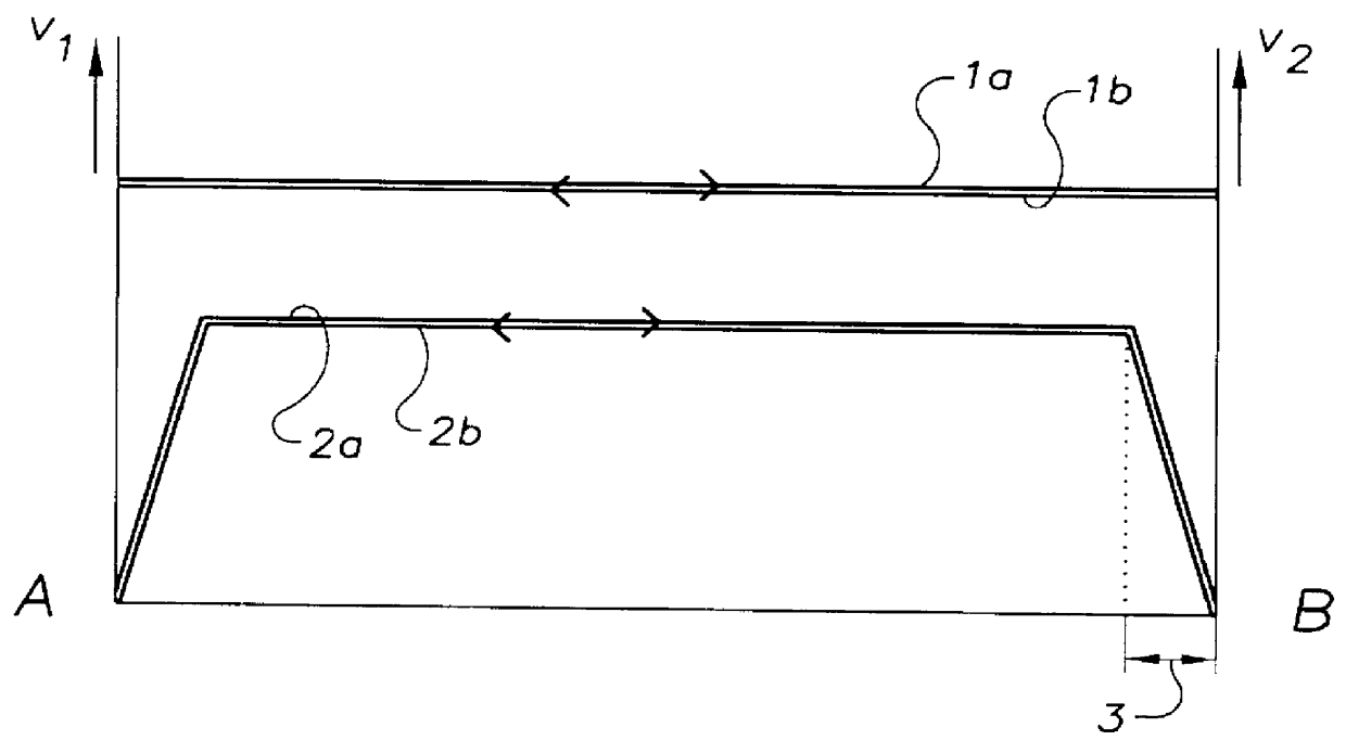
The preform peripheral velocity v.sub.1 and the burner block translational velocity v.sub.2 are regulated according to the example explained by FIG. 1. A constant surface temperature base value of 1,250.degree. C. is maintained at the preform surface during the deposition process. In addition, in this example the flame temperature of the hydrolysis burners is being varied in the turnaround point area of the burner block motion.

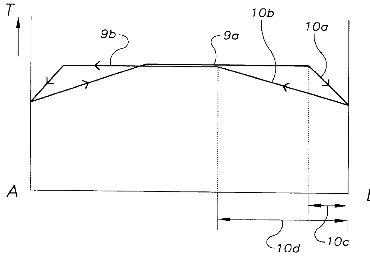
The variation of the flame temperature is controlled by a program and is explained by means of FIG. 3. The flame temperature "T" of the hydrolysis burners is plotted in relative units on the y-axis.

In a central area between the turnaround points A, B (curve sections 9a, 9b) the flame temperature is kept at a high level. During the forward motion of the burner block, for example in the direction toward the turnaround point B and approximately 3 cm before it, the flame temperature is continually lowered in a transitional area 10c (curve section 10a). The transit...

example 4

The deposition parameters illustrated by the example in FIG. 4 are set according to the process variant described by way of FIG. 3. However, in contrast to the temperature profile "T" represented in FIG. 3, the flame temperature is being constantly varied by programmed control during the motion cycle. Therefore the areas of constant flame temperature (curve sections 9a and 9b in FIG. 3) are absent in this temperature profile.

During the forward motion of the burner block toward the turnaround point B the burner flame reaches its maximal temperature at a point 11a, approximately 6 cm before the turnaround point B. Afterward the flame temperature is continually reduced in a transitional area 12c (curve section 12a) and reaches its minimum temperature at the turnaround point B. Thus the transitional area 12c ends there. The lowering of the flame temperature takes place according to the process variants described above by way of FIG. 3.

During the reverse travel of the burner block the fl...


PUM

PropertyMeasurementUnit
Speedaaaaaaaaaa
Speedaaaaaaaaaa
Speedaaaaaaaaaa

Abstract

PCT No. PCT/EP97/03818 Sec. 371 Date Mar. 3, 1998 Sec. 102(e) Date Mar. 3, 1998 PCT Filed Jul. 17, 1997 PCT Pub. No. WO98/03440 PCT Pub. Date Jan. 29, 1998In a known process for the production of quartz glass bodies, SiO2 particles are deposited of the mantle surface of a cylindrical carrier rotating about its longitudinal axis, forming an elongated, porous preform, where the SiO2 particles are formed in a plurality of flame hydrolysis burners which are arranged in at least one burner row parallel to the longitudinal axis of the carrier and are moved at a preset translational speed forward and back between turnaround points at which points their direction of movement is reversed, and in which process the preform is sintered. In order to make available on this basis an easily accomplished process that makes it possible to manufacture a preform which is largely free of localized density variations, the invention proposes on the one hand that the base value of the surface temperature of the preform being formed be kept in a range between 1,050 DEG C. and 1,350 DEG C., that the average peripheral velocity of the preform be kept in the range between 8 m/min and 15 m/min and the average translational velocity of the burner row be kept in a range between 300 mm/min and 800 mm/min. On the other hand, the object is also accomplished according to the invention and on the basis of the known process in that in the area of the turnaround points (A, B) the peripheral velocity of the preform being formed is increased and/or the flame temperature is lowered and/or the distance of the burners from the preform surface is changed.

Description

The invention relates to a process for the production of quartz glass bodies by deposition of SiO.sub.2 particles on the mantle surface of a cylindrical carrier rotating about its longitudinal axis and forming an elongated porous preform, where the SiO.sub.2 particles are formed in a plurality of hydrolysis burners which are arranged in at least one burner row disposed parallel to the longitudinal axis of the carrier and between turnaround points at which points the direction of burner movement is reversed, where the burners move at a preset translational speed forward and back, and by the sintering of the preform.DISCUSSION OF PRIOR ARTSuch a process is described in EP A1 0 476 218. In the known process, SiO.sub.2 particles are deposited in layers by flame hydrolysis burners on a horizontally oriented substrate rod which rotates about its longitudinal axis. The burners are installed equidistantly 10 cm apart on a burner block extending parallel to the longitudinal axis of the subst...

Claims


Application Information

Patent Timeline
IPC IPC(8): C03B19/00C03B19/14C03B37/014C03B8/04C03B20/00C03B37/018
CPCC03B19/1423C03B37/01413C03B37/0142C03B37/01486C03B2207/70C03B2207/52C03B2207/62C03B2207/66C03B2207/36C03B2207/54C03B20/00C03B37/014
Inventor SCHAPER, HARTWIGRUPPERT, KLAUS
Owner HERAEUS QUARZGLAS
Why Eureka
Try Eureka