Method and apparatus for generating a driver signal for use by a non-linear class S amplifier for producing linear amplification

a non-linear amplifier and driver signal technology, applied in the field of linear transmitters, can solve the problems of low power efficiency of such amplifiers, loss or distortion of amplitude information carried by the amplitude component of input signals, and no simple techniques presently exist to allow the use of highly efficient class s amplifiers

Inactive Publication Date: 2000-04-11
LUCENT TECH INC
View PDF4 Cites 13 Cited by
  • Summary
  • Abstract
  • Description
  • Claims
  • Application Information

AI Technical Summary

Problems solved by technology

The drawback of using linear amplifiers, however, is the low power efficiency associated with such amplifiers.
The problem with these alternate schemes is that although non-linear amplifiers exhibit increased power efficiency over linear amplifiers, they lose or distort amplitude information carried by the amplitude c

Method used


Image

  • Method and apparatus for generating a driver signal for use by a non-linear class S amplifier for producing linear amplification
  • Method and apparatus for generating a driver signal for use by a non-linear class S amplifier for producing linear amplification

Examples


Embodiment Construction

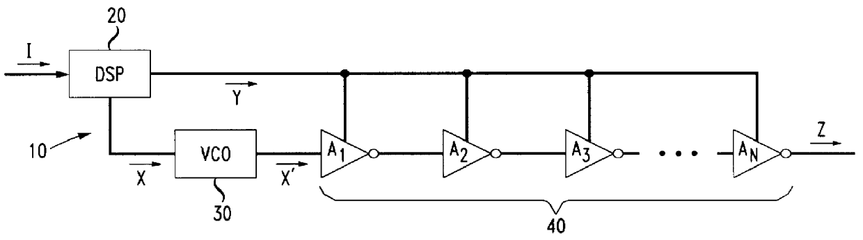
A block representation of a modulator circuit 10 in accordance with a preferred embodiment of the present invention is shown in FIG. 1. The modulator circuit includes a voltage controlled oscillator (VCO) 30 and a driver section 40. An input signal I is decomposed into a phase component (X) having a constant amplitude, and an amplitude component (Y) having a constant phase. The decomposing of the input signal can be readily accomplished by using known digital signal processing techniques as is known by those having ordinary skill in the art.

Once the input signal is decomposed, the phase component X is used to drive the VCO 30. As a result, VCO 30 outputs a signal X' which is a phase modulated carrier signal having a constant amplitude. The signal X' contains data carried by the phase component X of the input signal and is then provided as an input to the driver stage 40.

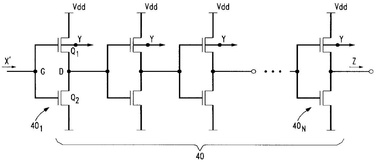
As shown, driver stage 40 includes a plurality of driver stages 40.sub.1 -40.sub.N made up of variable threshold i...


PUM


Abstract

A circuit for receiving an input signal having a phase component and an amplitude component which carry information, and for producing an output driver signal containing the phase and amplitude component information for driving a non-linear amplifier for generating linear amplification. The circuit includes a voltage controlled oscillator for receiving the phase component and for outputting a phase modulated carrier signal having a duty cycle and a constant amplitude. A driver stage made from a plurality of invertors, each having a pair of MOSFET transistors, receives the carrier signal at the gate terminals of the transistors. The amplitude component is used to drive the invertors by applying the amplitude component to the backgate terminals of at least some of the transistors in the invertors to pulse width modulate the carrier signal. The resulting output signal containing both phase component information and amplitude component information can then be used to drive a non-linear Class S amplifier to generate linear amplification while achieving high efficiency.

Description

1. Field of the InventionThe present invention relates to a linear transmitter for providing amplitude and phase modulation to an input signal. More particularly, the present invention pertains to a device and method for generating a driver signal for driving a non-linear amplifier and for producing linear amplification.2. Description of the Related ArtMany modulation schemes for transmitting modulated phase and modulated amplitude components of an input signal in communications systems are known. In some schemes, linear transmitters employing linear amplifiers are used because such amplifiers preserve the phase and amplitude components of the input signal and, consequently, the data contained therein. The drawback of using linear amplifiers, however, is the low power efficiency associated with such amplifiers. Other prior art schemes attempt to simulate linear transmitter performance using non-linear amplifiers so as to benefit from the higher power efficiency that non-linear ampli...

Claims


Application Information

Patent Timeline
IPC IPC(8): H03F1/02H03F3/217H03F3/20
CPCH03F3/2171H03F1/0211
Inventor GLAS, JACKWANG, HONGMO
Owner LUCENT TECH INC
Why Eureka
Try Eureka