Driver that efficiently regulates current in a plurality of LED strings

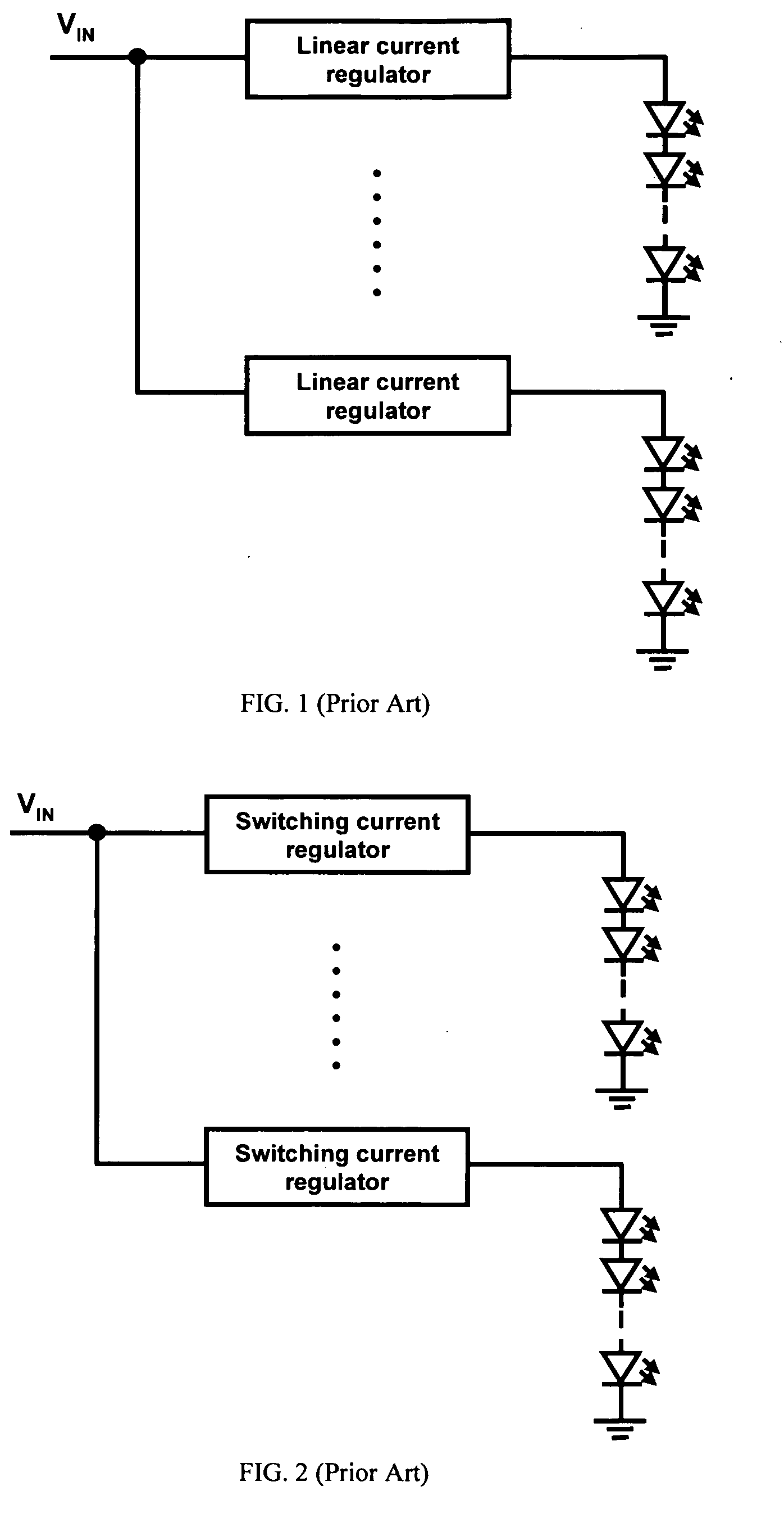
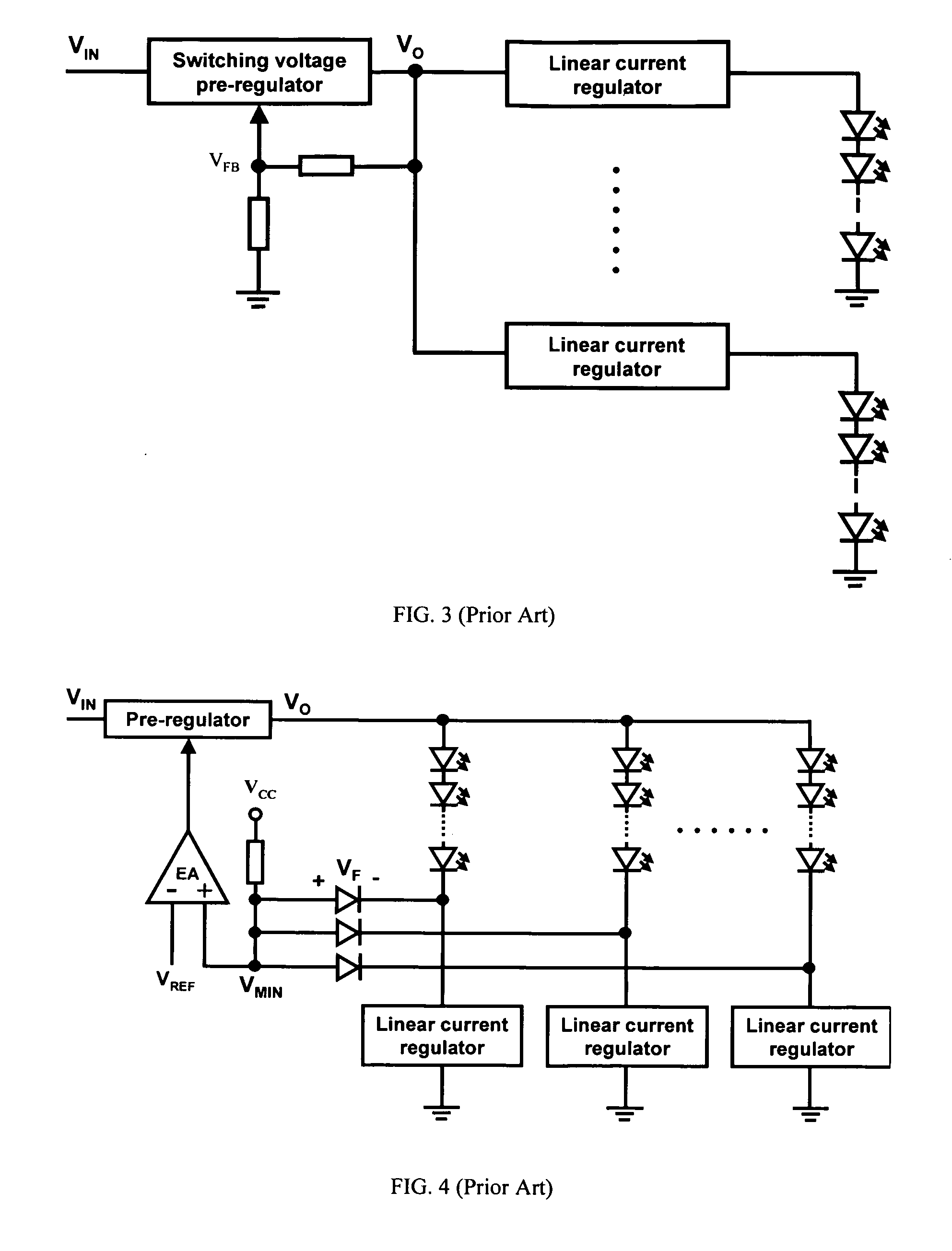
a technology of led string and driver, which is applied in the direction of lighting apparatus, instruments, light sources, etc., can solve the problems of poor efficiency of circuit fig. 1, simple paralleling of leds or led strings is not desirable, and the output voltage of power supply is reduced, so as to achieve the effect of optimum operating efficiency, improving the performance of the driver, and reducing the output voltage of the power supply

Inactive Publication Date: 2009-07-23
DELTA ELECTRONICS INC
View PDF10 Cites 222 Cited by
  • Summary
  • Abstract
  • Description
  • Claims
  • Application Information

AI Technical Summary

Benefits of technology

[0013]According to other more detailed features of the invention, the power supply comprises a switching pre-regulator, such as a SEPIC (single-ended primary inductance converter). The output of the switching power supply is controlled by the duty cycle of a pulse-width-modulated (PWM) signal, where the duty cycle of the PWM signal is changed in response to the feedback signal. At least one the plurality of the current regulating transistors co

Problems solved by technology

However, a major drawback of series connection of LEDs is the cumulative voltage drop that eventually limits the number of LEDs in series.
On the other hand, simple paralleling of LEDs or LED strings is not desirable because of current sharing problems related to the LED's exponential voltage-current characteristic with a negative temperature coefficient of the forward voltage.
Because of the requirement for lower total voltage for forward biasing the LEDs in each string relative to the supply voltage, however, the circuit of FIG. 1 has poor efficiency especially when the voltage drops across the linear current regulators are high.
Although this approach has a higher operating efficiency, it also has a higher component count and cost when drivi

Method used


Image

  • Driver that efficiently regulates current in a plurality of LED strings
  • Driver that efficiently regulates current in a plurality of LED strings
  • Driver that efficiently regulates current in a plurality of LED strings

Examples


Embodiment Construction

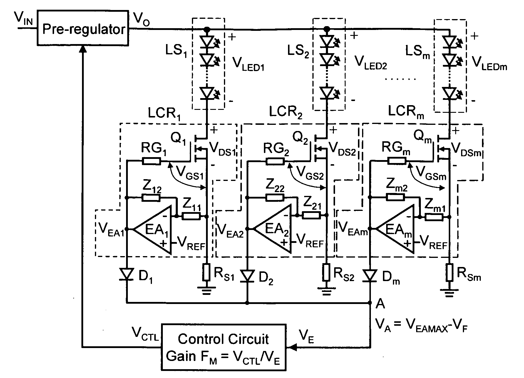
[0040]An LED driver circuit according to the present invention uses a power supply having an adjustable output voltage, such as a switching pre-regulator, coupled to a plurality of parallel LED strings, or other kind of loads, comprising one or more LEDs to generate corresponding plurality of current flows in each LED string. Each LED string has a cumulative forward voltage that is the sum of the forward voltage of the one or more LEDs. Thus, each load is associated with a corresponding voltage drop. In one embodiment, each LED string comprises a sequence of a plurality of serially coupled LEDs of the same or different colors such that the anode of one LED in the sequence is coupled to the cathode of another LED in the sequence. A plurality of Linear Current Regulators (LCRs), each serially coupled to an LED string, regulate the current flow through each LED string.

[0041]In one embodiment and as further described below, each LCR of an LED string includes a current regulating transis...


PUM


Abstract

A light-emitting diode (LED) driver according to the present invention consists of a voltage pre-regulator and multiple linear current regulators with an adaptively-controlled drive voltage. In this LED driver, the efficiency maximization is achieved by eliminating the sensing of the voltage drops across the linear regulators, i.e., by removing the external voltage feedback for the adjustment of the output voltage of the pre-regulator. In the LED driver of the present invention, the self-adjustment of drive voltage is achieved by relying on a relatively strong dependence between the gate-to-source and drain-to-source voltages of a current-regulating transistor, e.g., a MOSFET, operating in the linear region. The driver powers all LEDs in a string with a constant current and provides consistent illumination and optimum operating efficiency at low cost over a wide range of input/output voltage and temperature.

Description

FIELD OF THE INVENTION[0001]This invention relates to an LED driver, more specifically, to an LED driver that regulates current in LED strings.BACKGROUND OF THE INVENTION[0002]A light-emitting diode (LED) is a semiconductor device that emits light when electrically biased in the forward direction of its p-n junction. The color of the emitted light depends on the composition and condition of the semiconducting material used, and can be infrared, visible, or near-ultraviolet.[0003]LED backlighting is used in small, inexpensive Liquid Crystal Display (LCD) panels. The light is usually colored, although white LED backlighting is becoming more common. LED backlighting in larger displays helps to improve the color representation of the LCD display. LED light is created by separate LEDs to produce a color spectrum that closely matches the color filters in the LCD pixels themselves. The advantages of LED backlighting are extremely long life (100K hours vs. 30K hours for typical CCFL backlig...

Claims


Application Information

Patent Timeline
IPC IPC(8): G09G3/36
CPCH05B33/0815Y02B20/347H05B33/0827H05B33/0818H05B45/347H05B45/3725H05B45/46Y02B20/30
Inventor HU, YUEQUANJOVANOVIC, MILAN M.WENG, COLIN
Owner DELTA ELECTRONICS INC
Why Eureka
Try Eureka