Suction cylinder which transfers fiber web from a conveyer belt to two calendering cylinders

Inactive Publication Date: 2000-04-18
THIBEAU
View PDF13 Cites 61 Cited by
  • Summary
  • Abstract
  • Description
  • Claims
  • Application Information

AI Technical Summary

Benefits of technology

In the ambit of the invention, it is possible to position the suction cylinder at a level flush with the end portion of the conveyor belt, and in line with said belt. However, that variant suffers from the drawback of running the risk of the fiber web being unsupported on passing from the conveyor belt to the surface o

Problems solved by technology

On being transferred, and while in the intermediate zone between the conveyor belt and the calendering cylinders, the web is unsupported, and that is harmful to its cohesion.
In addition, in the intermediate zone, the conveyor belt and the calendering cylinders generate air turbulence because they are in motion, and the greater the speed of the conveyor belt and of the calendering cylinders, the greater the turbulence, which gives rise to an increased risk of transverse creases forming in the web while it is being transferred.
Such prior compression of the fiber web serves to attenuate the effects of the zone of turbulence, but it does not prevent the web being unsupported while it is being

Method used


Image

  • Suction cylinder which transfers fiber web from a conveyer belt to two calendering cylinders

Examples


Embodiment Construction

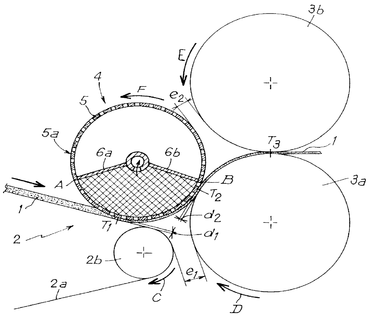
As can be seen in, the particular example shown in the FIGURE, a non consolidated fiber web 1 from a carder (not shown) is conveyed by a conveyor belt 2 to the vicinity of two heating calendering cylinders 3a and 3b. In conventional manner, the surfaces of the calendering cylinders 3a and 3b are raised to a temperature that is close to the softening temperature of the fibers of the web, so as to heat-bond the fibers together by compression and by heating as the web passes between the two calendering cylinders. The conveyor belt 2 comprises, in conventional manner, an endless belt 2a tensioned between drums (only one drum 2b illustrated) that are rotated. The belt 2a is impermeable to air and may be made of polypropylene, for example. In the figure, only the end portion of the conveyor belt in the vicinity of the two calendering cylinders 3a and 3b is shown.

In accordance with the invention, the fiber web 1 is transferred from the conveyor belt 2 to the two calendering cylinders 3a an...


PUM


Abstract

A fiber web transferring device comprising a conveyor belt, a suction cylinder, a lower calendering cylinder and an upper calendering cylinder. The suction cylinder having a stationary suction sector and rotates in a direction which corresponds to a linear moving direction of the conveyor belt. The suction cylinder transfers a non-consolidated fiber web from the conveyor belt to the lower calendering cylinder and is substantially tangential to the lower calendering cylinder so as to cooperate therewith to define a pre-calendering zone for the fiber web. The suction cylinder is positioned such that the suction cylinder sucks the fiber web from the conveyor belt and holds the fiber web against the outer surface of the suction cylinder to the pre-calendering zone. The fiber web then adheres to the outer surface of the lower calendering cylinder past the pre-calendering zone until the fiber web reaches the upper calendering cylinder.

Description

The present invention relates to transferring a fiber web from a conveyor belt to two calendering cylinders. More particularly, it relates to a novel use of a suction cylinder for performing such a transfer. The invention is particularly applicable to conveyor belts interposed between the outlet of a carder and the calendering cylinders.It is conventional for a fiber web leaving a carder to be conveyed to the calendering cylinders for consolidating the web by means of a conveyor belt. Until now, the fiber web has been transferred from the conveyor belt to the two calendering cylinders by the web being taken up directly by the calendering cylinders, with the conveyor belt extending so as to be tangential to the two calendering cylinders.On being transferred, and while in the intermediate zone between the conveyor belt and the calendering cylinders, the web is unsupported, and that is harmful to its cohesion. In addition, in the intermediate zone, the conveyor belt and the calendering...

Claims


Application Information

Patent Timeline
IPC IPC(8): D01G15/00D01G25/00D01G15/46B65H20/12D21F3/10
CPCD01G25/00D01G15/465
Inventor BRABANT, MARCDUPONT, JEAN-LOUIS
Owner THIBEAU
Why Eureka
Try Eureka