Laminated capacitor

a technology of laminated capacitors and capacitors, which is applied in the direction of fixed capacitors, stacked capacitors, fixed capacitor details, etc., can solve the problems of low breakdown voltage per unit thickness of element thickness, small electrostatic capacity which can be obtained, and insufficient performance of these capacitors

Inactive Publication Date: 2000-04-18
MURATA MFG CO LTD
View PDF3 Cites 80 Cited by
  • Summary
  • Abstract
  • Description
  • Claims
  • Application Information

AI Technical Summary

Problems solved by technology

However, the conventional laminated capacitors shown in FIGS. 3 and 4 have had problems in that because a thickness of the dielectric interposed between the internal electrodes (hereinafter referred to as "element thickness") must be increased considerably to design a high-voltage withstanding capacitor, not only the value of breakdown voltage per unit thickness of the element thickness becomes low but also the electrostatic capacity which can be obtained becomes small as the element thickness increases.
Accordingly, the performance of these capacitors is not adequate.
However, the laminated capacitor described above has had a problem in that when a distance D between edges X of the external terminals 4a and 4b and an edge a of the floating internal electrode 2c closest to the external terminals 4a and 4b among the floating internal electrodes 2c in the outermost layer is reduced below a certain degree, flashover occurs between the edges X--X of the external terminals 4a and 4b and the value of AC breakdown voltage drops.
Further, this capacitor has had a problem in that when the distance D between X-a is increased, the number of internal electrodes to be laminated must be increased to obtain a desired capacitance because an overlapped area of the internal electrodes decreases for the size of the dielectric.
There has also been a problem that the AC breakdown voltage drops when the number of internal electrodes to be laminated increases.
The conventional laminated capacitor described above has had other problems because the dielectric strength performance drops when each gap G between the internal electrodes on the same plane is reduced below a certain degree and because the distance between X-a is reduced and flashover is liable to occur between the edges X--X when the gap G is increased because the floating internal electrode approaches the external terminal.
However, according to the experiments, it has been difficult to assure enough reliability as a product just by setting the gap G of the internal electrodes at two times the element thickness t because the value of breakdown voltage is dispersed in a breakdown voltage (BDV) test.
Then, when the distance D between X-a is increased in order to avoid such a problem, the overlapped area of the internal electrodes becomes small for the size of the dielectric and the desired capacitance cannot be obtained.
When the number of internal electrodes to be laminated is increased in order to compensate for this, the probability of causing pinholes increases, and the breakdown voltage drops.
It then becomes difficult to maintain enough reliability as a product.

Method used


Image

  • Laminated capacitor
  • Laminated capacitor
  • Laminated capacitor

Examples


Embodiment Construction

A preferred embodiment of the present invention will be described below to explain the inventive characteristics thereof in detail.

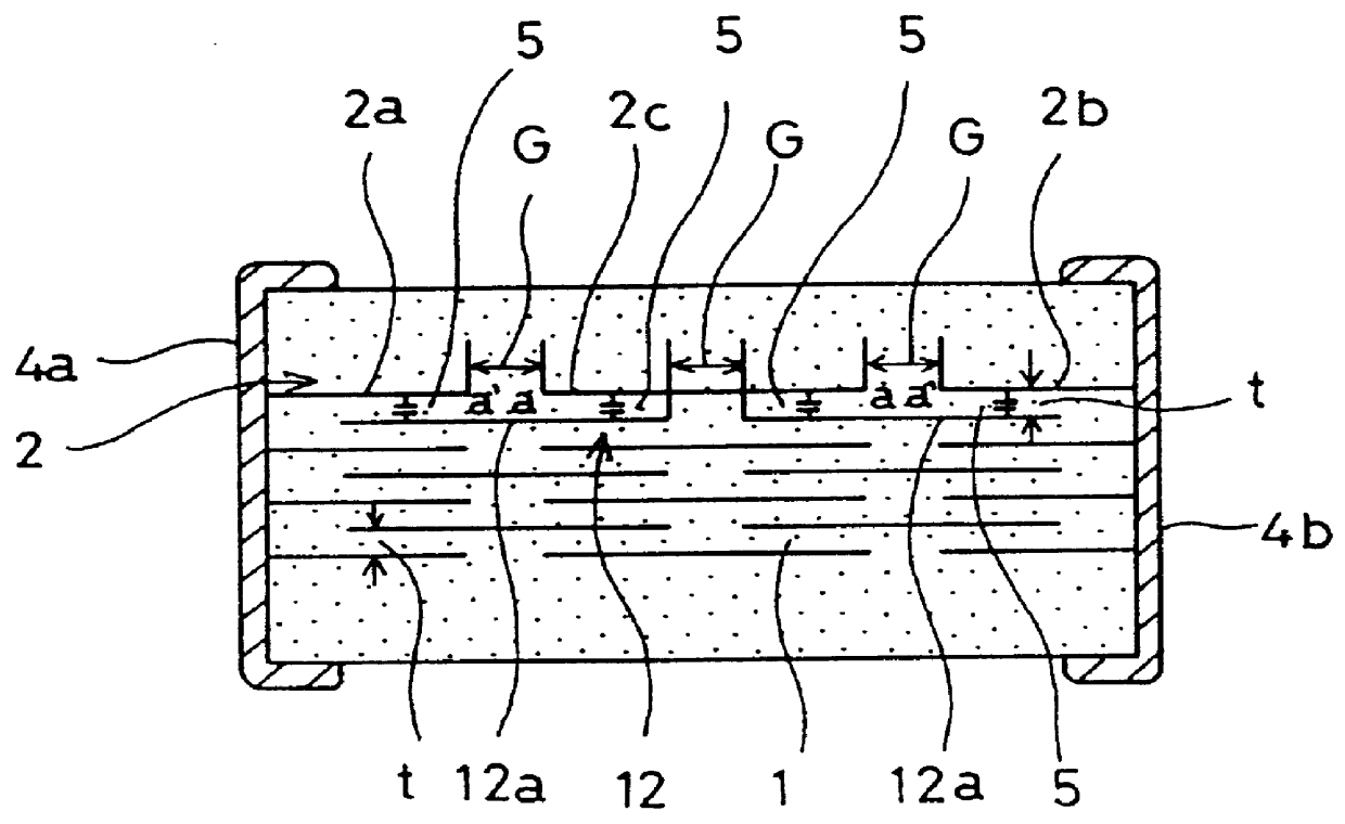
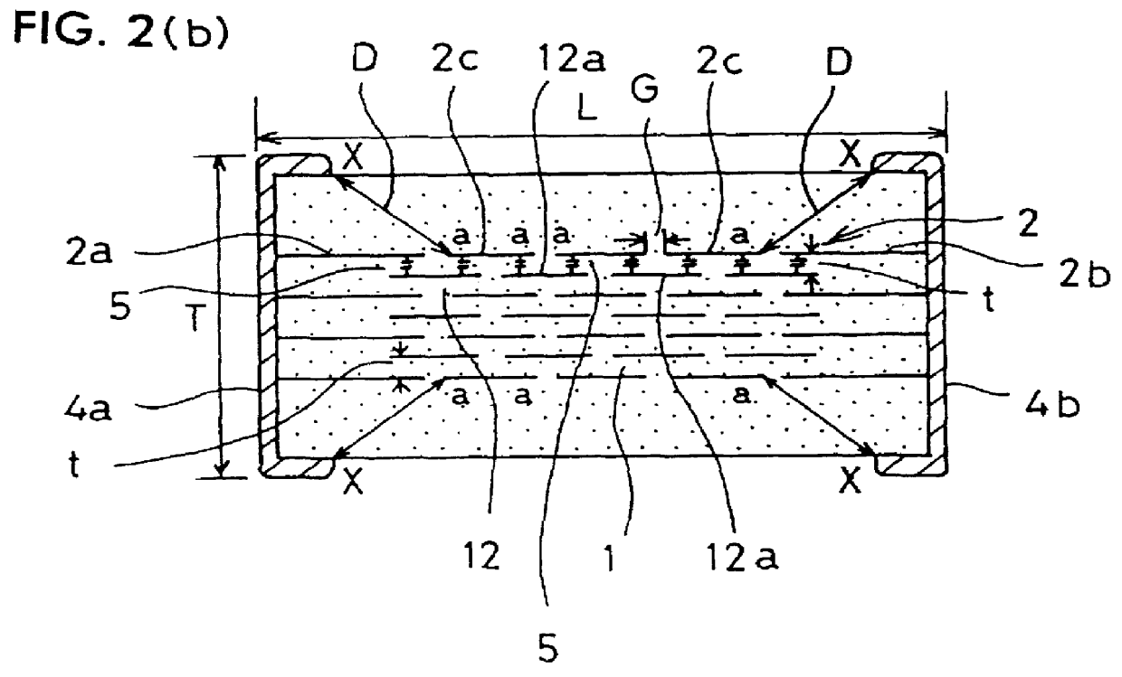
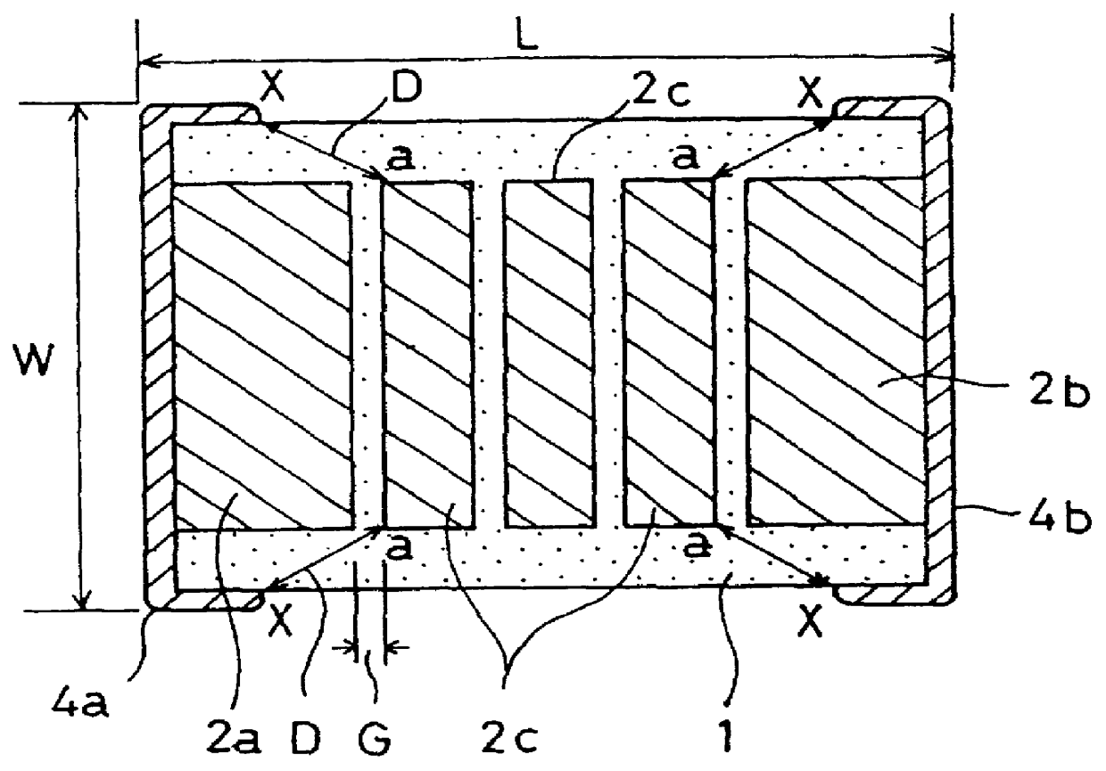
A laminated capacitor as shown in FIG. 1 was fabricated at first in order to study the relationship between each gap between internal electrodes in the same plane and the value of AC breakdown voltage. This laminated capacitor has a quadruple series structure (four capacitors in each serial grouping) and is formed by alternately disposing first internal electrode groups 2 each comprising a first connected internal electrode 2a connected with one external terminal 4a, a second connected internal electrode 2b connected with another external terminal 4b and a floating internal electrode 2c positioned between the first and second connected internal electrodes 2a and 2b in the same plane and second internal electrode groups 12 each comprising a plurality (two here) of floating internal electrodes 12a disposed in a plane facing the first internal electrode gro...


PUM

PropertyMeasurementUnit
distanceaaaaaaaaaa
distanceaaaaaaaaaa
distanceaaaaaaaaaa

Abstract

A laminated capacitor that can be made small in size, that can prevent flashover, has excellent dielectric strength performance and a large capacitance is disclosed. Each gap between internal electrodes in the same plane is set at 2.7 to 20 times a thickness (element thickness) of a dielectric layer positioned between first and second internal electrode groups which face each other and a distance between an edge of the external terminal and an edge of the floating internal electrode closest to the external terminal among floating internal electrodes of the internal electrode group of the outermost layer is set at 0.4 mm to 1.4 mm.

Description

1. Field of the InventionThe present invention relates to a laminated capacitor and more particularly to a small, high-withstanding and high-capacity laminated capacitor.2. Description of Related ArtA laminated capacitor is shown in FIG. 3 known from the prior art. The capacitor has a structure in which external terminals 54a and 54b conduct with internal electrodes 52a and 52b, respectively in an alternating manner. The capacitor comprises a chip 53 in which a dielectric (layer) 51 and the internal electrodes 52a and 52b are laminated alternately as shown in FIG. 3. In another embodiment of the prior art capacitor, as shown in FIG. 4, a double series structure is used in which a floating internal electrode 62 which is not connected with the external terminals 54a or 54b is disposed. The floating electrode 62 is serially connected such that two dual capacitor sections 55 are formed between the internal electrodes 52a and 52b disposed so as to face each other via the dielectric 51 co...

Claims


Application Information

Patent Timeline
Patent Type & Authority Patents(United States)
IPC IPC(8): H01G4/38H01G4/30H01G4/12
CPCH01G4/385H01G4/30H01G4/06
Inventor KURODA, YOICHIHONDA, YUKIOOSUGA, KAZUMI
Owner MURATA MFG CO LTD
Why Eureka
Try Eureka