Al technical title is built by PatSnap Al team. It summarizes the technical point description of the patent document.
a body fluid and sampling device technology, applied in medical science, vaccination/ovulation diagnostics, surgery, etc., can solve the problems of difficult blood transfer directly to the test device, less likely to provide excellent blood samples, and significant pain in many patients
Inactive Publication Date: 2000-05-02
ROCHE DIABETES CARE INC
View PDF6 Cites 277 Cited by
Summary
Abstract
Description
Claims
Application Information
AI Technical Summary
This helps you quickly interpret patents by identifying the three key elements:
Problems solved by technology
Method used
Benefits of technology
Problems solved by technology
However, the nerve density in this region causes significant pain in many patients.
These sites are also less likely to provide excellent blood samples and make blood transfer directly to test devices difficult.
Repeated lancing in limited surface areas (such as fingertips) results in callous formation.
This leads to increased difficulty in drawing blood and increased pain.
In such situations, bringing the finger of a patient directly to the test device poses some risk of contamination from blood of a previous patient.
However, it will be appreciated that the incision will tend to close against the syringe, thereby limiting any advantage that can be achieved.
The amount of fluid which can be obtained in that way is very limited, however.
Even with the many improvements which have been made, the pain associated with lancing remains a significant issue for many patients.
The need for blood s
Method used
Image
Click on the blue label to locate the original text in one second.
Reading with bidirectional positioning of images and text.
Examples
Embodiment Construction
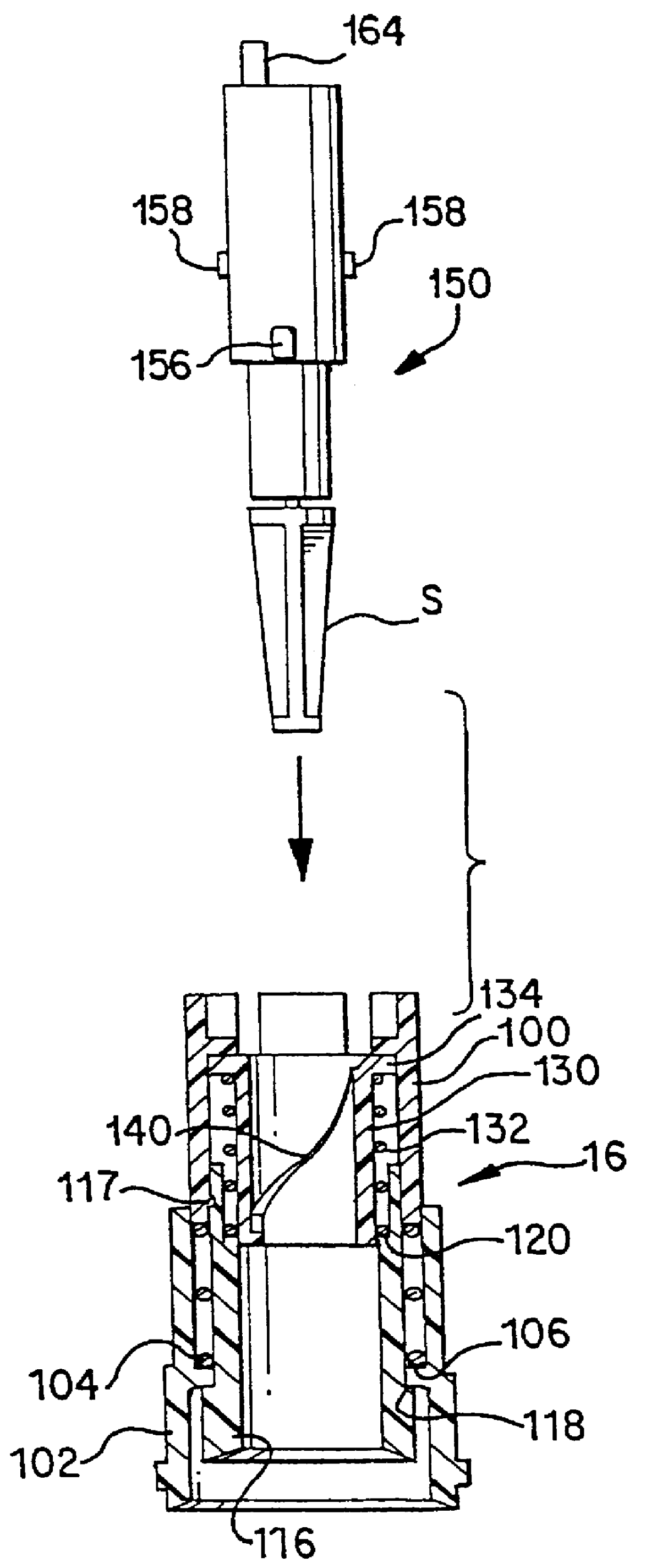
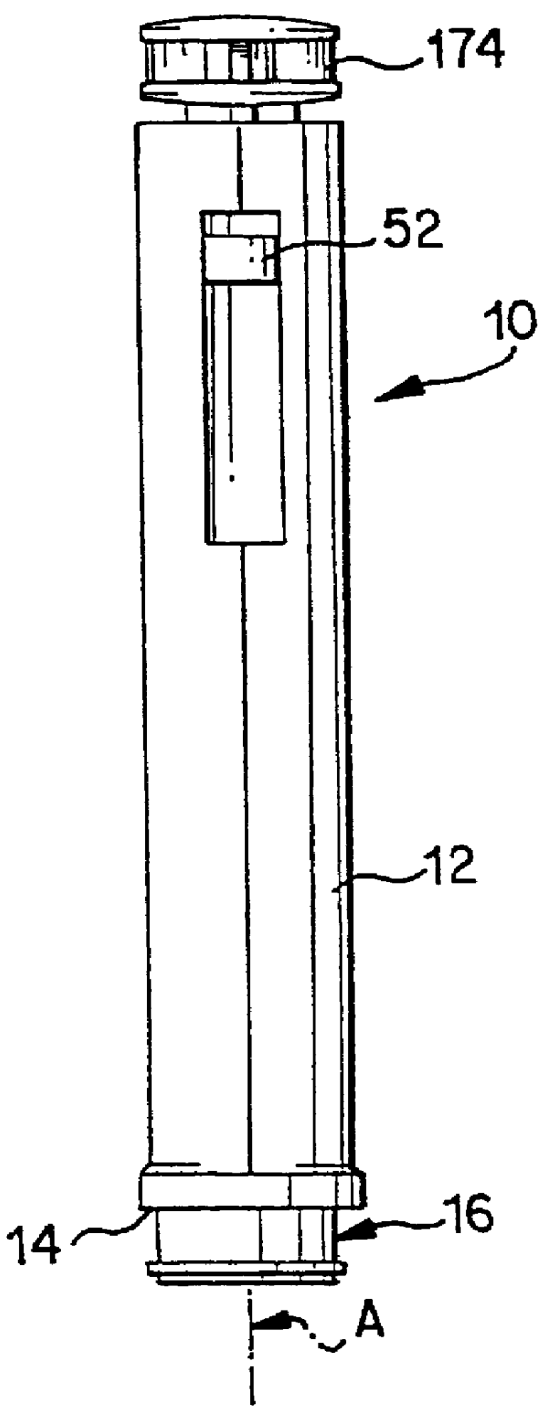
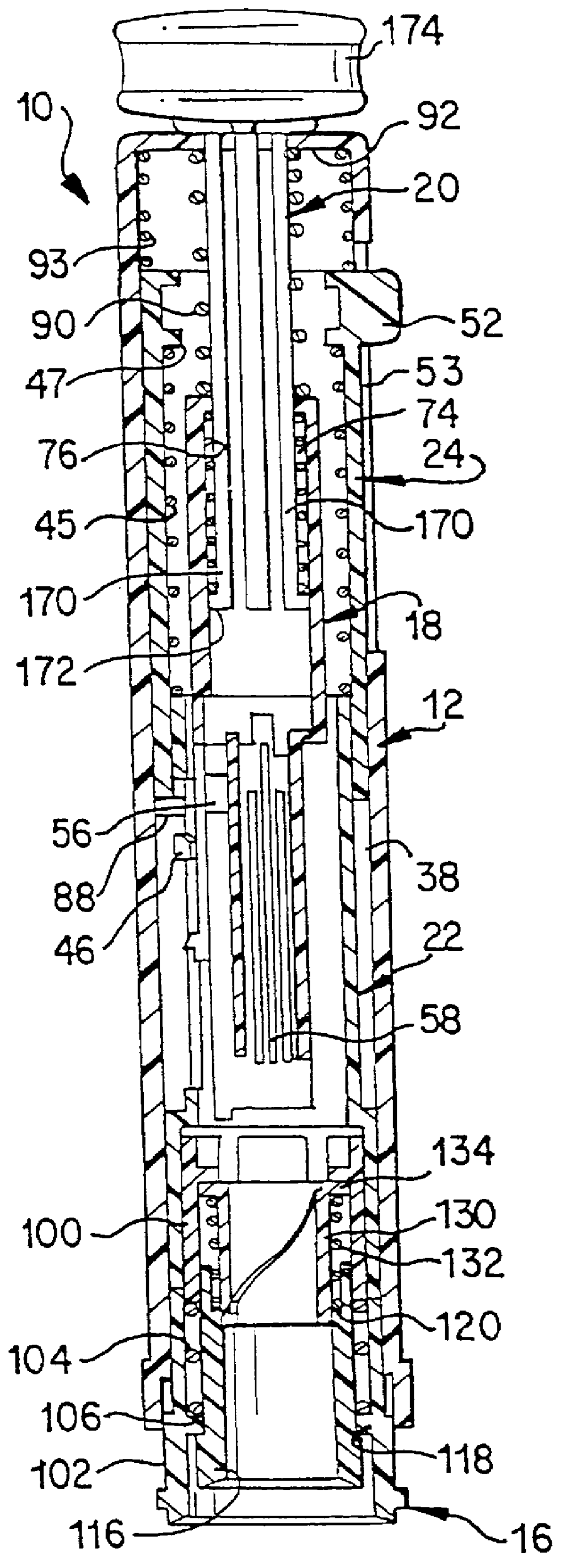
A minimally invasive sampling device 10 shown in FIG. 1, includes a tubular housing 12 formed of two half-shells 12A, 12B (see FIGS. 9 and 10) that are secured together. The housing 12 defines a longitudinal axis A and a lower open end 14 adapted to receive a removable lancet carrier unit 16. That carrier unit serves to carry a disposable lancet member 150 and to stimulate a skin puncture site, as will be explained subsequently.
Also mounted in the housing 12 (see FIG. 3A) are a hammer 18 for displacing the disposable lancent member downwardly in a skin-piercing direction, a manual handle 20 for raising the hammer to a cocked (i.e., downwardly biased) position, an interposer 22 for automatically releasing the hammer in response to a manual pushing of the device against a skin surface, a manually actuable pusher 24 for pushing a blood-receiving capillary tube downwardly, and a plurality of springs for achieving proper placement and movement of the above-described parts.
The interposer ...
PUM
Abstract
A device for sampling body fluid includes a housing having a sleeve at a forward end thereof which is displaceable in response to being pressed against a user's skin to trigger the firing of a lancet. After the lancet is removed from the incision, the sleeve is repeatedly pressed against the skin to depress a ring of body tissue in surrounding relationship to the incision to express body fluid outwardly through the incision. A pusher member is then actuated to push a capillary tube through a front end of the housing for drawing-in body fluid. The lancet is a disposable lancet which includes a body supporting a skin-lancing member and the capillary tube. The disposable lancet passes through an upper end of a lancet carrier when being installed or removed. The device cannot be armed until the disposable lancet is installed in the housing, because the capillary tube functions to push a safety device to a non-safety position.
Description
PRIOR APPLICATIONSThis application claims benefit of applications Ser. No. 60 / 017,133 filed May 17, 1996; 60 / 019,918 filed Jun. 14, 1996; 60 / 023,658 filed Aug. 1, 1996; 60 / 025,340 filed Sep. 3, 1996; 60 / 714,548 filed Sep. 16, 1996; and 08 / 710,456 filed Sep. 17, 1996; 08 / 727,074 filed Oct. 8, 1996 the disclosures of which are incorporated herein by reference.The present invention is related to inventions disclosed in the following concurrently filed, commonly assigned U.S. applications: Ser. No. 08 / 858,045, entitled "Methods and Apparatus For Sampling Body Fluid" (attorney docket no. 018176-057); Ser. No. 08 / 857,335, entitled "Disposable Element for Use in a Body Fluid Sampling Device" (attorney docket 018176-058); Ser. No. 08 / 858,043 entitled "Methods and Apparatus For Sampling and Analyzing Body Fluid" (attorney docket 018176-059); and Ser. No. 08 / 858,043, entitled "Methods and Apparatus For Expressing Body Fluid from an Incision" (attorney docket 018176-060) and Serial No. 08 / 975,...
Claims
Application Information
Patent Timeline
Application Date:The date an application was filed.
Publication Date:The date a patent or application was officially published.
First Publication Date:The earliest publication date of a patent with the same application number.
Issue Date:Publication date of the patent grant document.
PCT Entry Date:The Entry date of PCT National Phase.
Estimated Expiry Date:The statutory expiry date of a patent right according to the Patent Law, and it is the longest term of protection that the patent right can achieve without the termination of the patent right due to other reasons(Term extension factor has been taken into account ).
Invalid Date:Actual expiry date is based on effective date or publication date of legal transaction data of invalid patent.