Teatcup

a technology of tetrafluoroethylene and tetrafluoroethylene, which is applied in the field of tetrafluoroethylene, can solve the problems of deterioration of elastic capacity, time-consuming, and difficult replacement operation of elastic materials,

Inactive Publication Date: 2000-05-09
DELAVAL HLDG AB
View PDF19 Cites 38 Cited by
  • Summary
  • Abstract
  • Description
  • Claims
  • Application Information

AI Technical Summary

Problems solved by technology

Every elastic material, at least such which are available today, is subjected to a deterioration of the elastic capacity over the time and by use.
Teatcups known do not function in a satisfactorily manner in this respect and this operation of replacement is difficult and time consuming.
In addition, it happens that the teatcup liner is not always mounted in a proper position in the shell, which means that the teatcup will not function in a optimal manner during the milking operation.
By such a mounting method it is difficult to demount and once again mount the valve housing to the other parts.
In addition, there is a great risk that the lower end of the teatcup liner will jam to the connection pipe over time due to the milk substances penetrating the joint therebetween.
A further disadvantage of this teatcup is the relatively long height which, especially during milking of smaller animals having a small distance between the gr

Method used


Image

  • Teatcup
  • Teatcup
  • Teatcup

Examples


Embodiment Construction

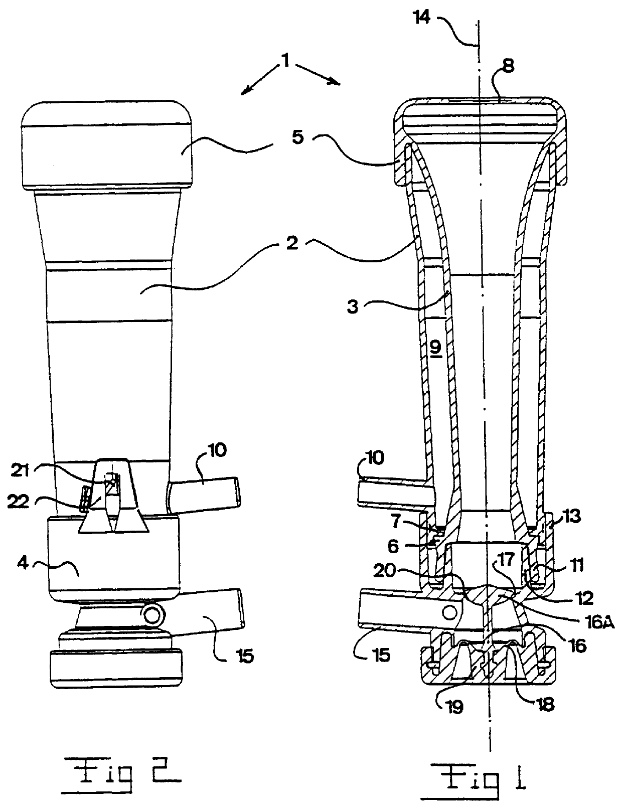
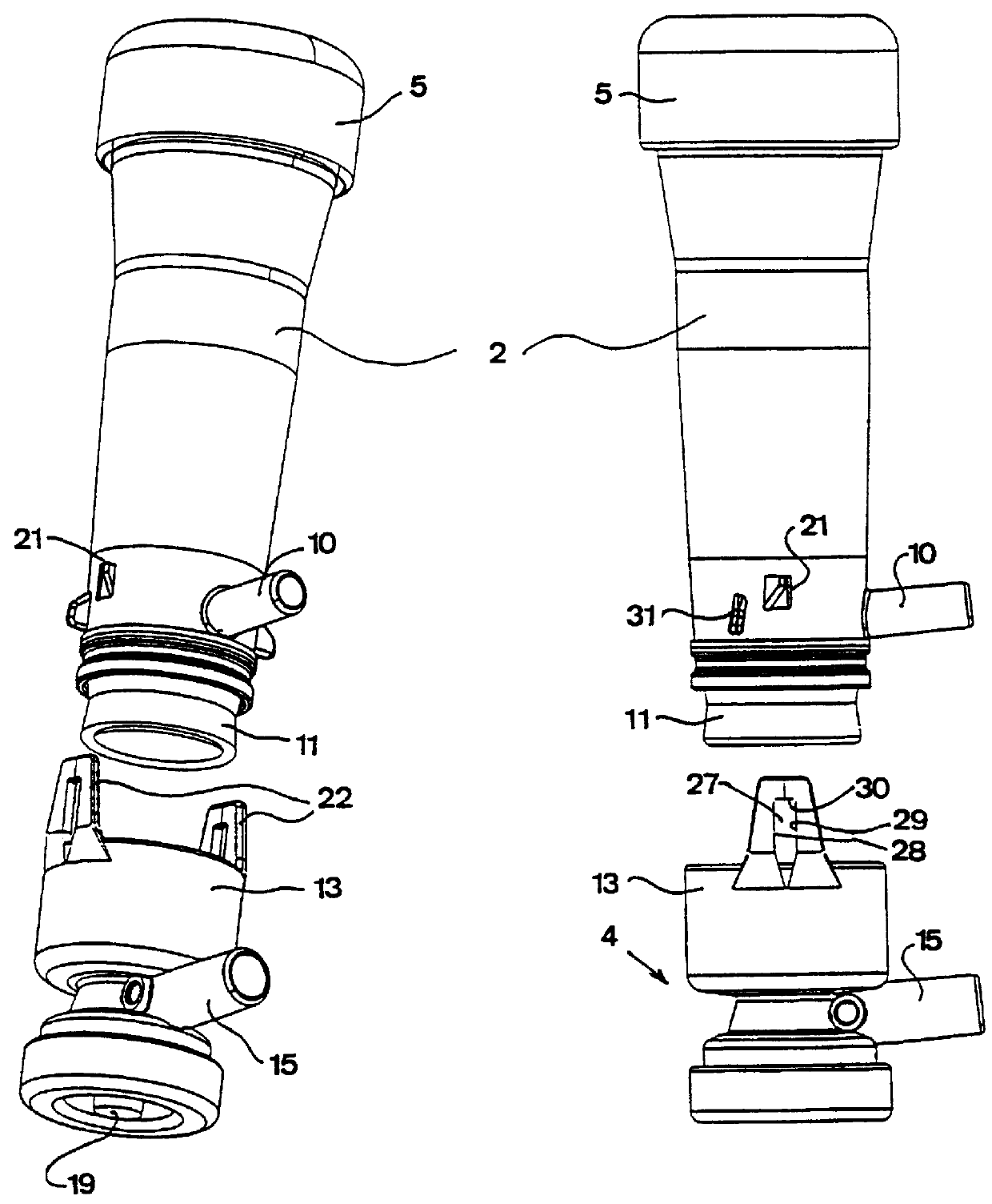
With reference to FIGS. 1-4, there is disclosed a teatcup 1 having a rigid outer shell 2, a tubular teatcup liner 3 extending in the shell 2 and a valve housing 4 mounted to the lower end of the shell 2. The teatcup liner 3 has an upper collar 5 arranged to abut the outer surface of the shell 2. The lower part of the teatcup liner 3 comprises a circumferential shoulder 6 projecting radially outwardly and arranged to abut a surrounding shoulder 7 projecting radially inwardly and provided on the inner surface of the shell 2. As is disclosed in FIG. 1 the teatcup liner 3 is thus fixedly held in a fixed position in the shell 2 by means of the collar 5 and the shoulder 6 projecting radially outwardly. Furthermore, the teatcup liner 3 has a passage 8 provided in the upper part for the application of the teatcup 1 to a teat. When the teatcup liner 3 is mounted in the shell 2 in the manner disclosed, there is formed a closed pulsation chamber 9 between the teatcup liner 3 and the shell 2. T...


PUM


Abstract

PCT No. PCT/SE97/00491 Sec. 371 Date Sep. 16, 1998 Sec. 102(e) Date Sep. 16, 1998 PCT Filed Mar. 21, 1997 PCT Pub. No. WO97/35469 PCT Pub. Date Oct. 20, 1997A teatcup (1) comprises a shell (2), a tubular teatcup liner extending in the shell and a valve housing (4) having a connection pipe connectable to an end (11) of the teatcup liner, a valve housing (4) being arranged to be mounted to the shell (2). The valve housing and the shell comprise locking members (21, 22), which are arranged to engage each other disconnectably during said mounting in order to lock the valve housing to the shell.

Description

1. Field of InventionThe present invention comprises a teatcup comprising a shell, a tubular teatcup liner extending in the shell, and a valve housing having a connection pipe connectable to an end of the teatcup liner, the valve housing being arranged to be mounted to the shell and the connection pipe being arranged to be inserted into said end of the tubular teatcup liner, the valve housing and the shell comprising locking members arranged to engage each other disconnectably during said mounting in order to lock the valve housing to the shell.2. Description of the Prior ArtA known milking machine comprises a number of teatcups to be applied to a respective teat of an animal to be milked. Usually, such a teatcup comprises an outer rigid shell and a tubular teatcup liner extending in the shell. When the teatcup is applied to a teat of an animal to be milked, the inner wall of the tubular teatcup liner will thus abut the teat. Since the teatcup liners shall provide a pulsating pressu...

Claims


Application Information

Patent Timeline
IPC IPC(8): A01J5/00A01J5/08A01M5/08A01M5/00F16L37/00F16L37/098
CPCF16L37/0985A01J5/08
Inventor MIEFALK, H.ANG.KAN SVEN UNO
Owner DELAVAL HLDG AB
Why Eureka
Try Eureka