

Adaptive antenna
a technology of adaptive antennas and antennas, applied in antennas, electrical equipment, radio transmission, etc., can solve problems such as complex circuit structur
- Summary
- Abstract
- Description
- Claims
- Application Information
AI Technical Summary
Benefits of technology
Problems solved by technology
Method used
Image

Examples
first embodiment
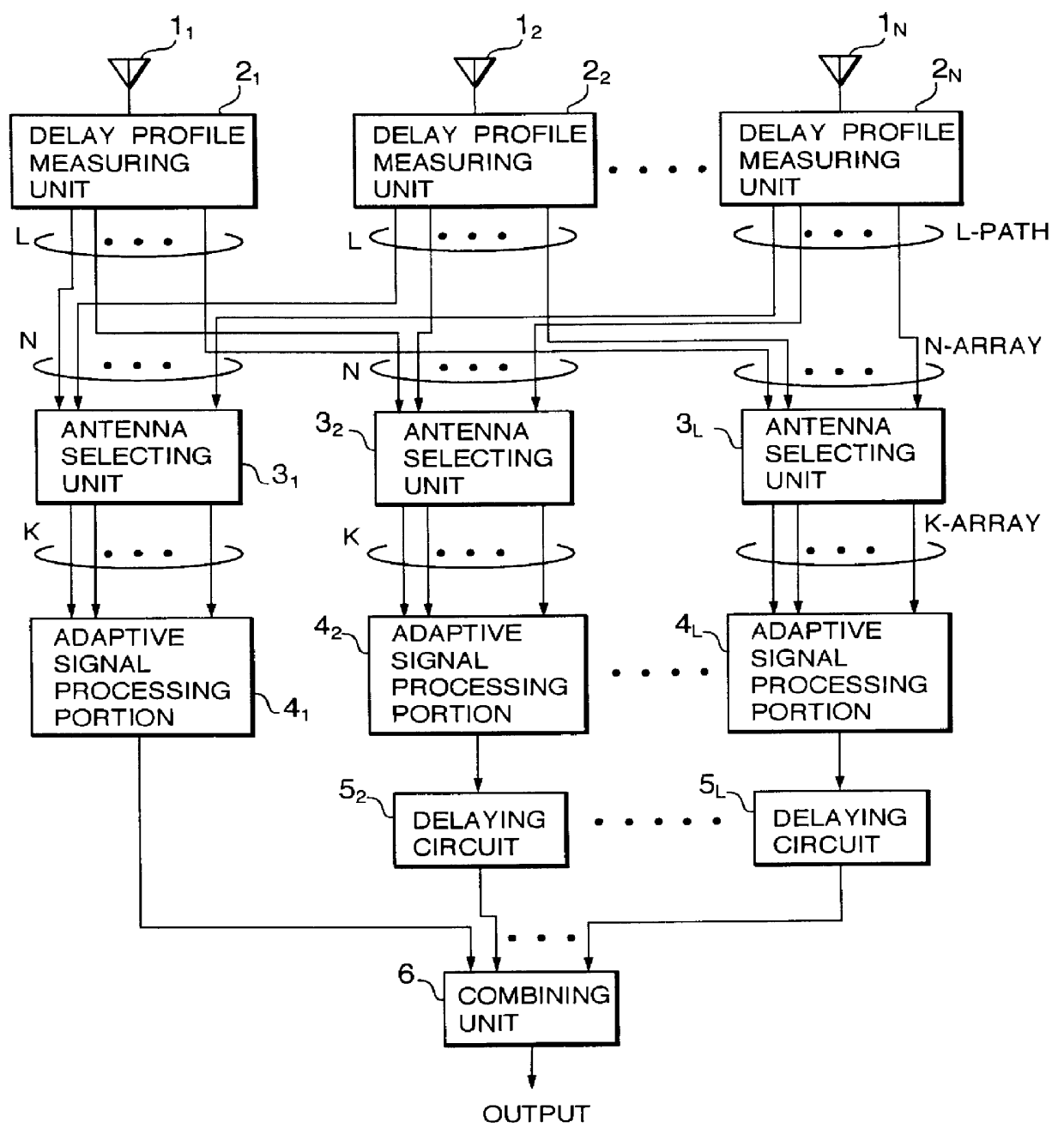
FIG. 1 is a schematic diagram showing the structure of an adaptive antenna according to the present invention.
N antenna elements 1.sub.1, 1.sub.2, . . . , and 1.sub.N that have respective directivity have respective beam directions. Alternatively, the adaptive antenna according to the present invention can be accomplished with omni-directional antenna elements.
The antenna elements 1.sub.1, 1.sub.2, . . . , and 1.sub.N are connected to delay profile measuring units 2.sub.1, 2.sub.2, . . . , and 2.sub.N, respectively. The delay profile measuring units 2.sub.1, 2.sub.2, . . . , and 2.sub.N generate delay profiles of the antenna elements 1.sub.1, 1.sub.2, . . . , and 1.sub.N with a correlating process using a known reference symbol placed in a transmission signal.
The delay profile measuring units 2.sub.1, 2.sub.2, . . . , and 2.sub.N extract signal components for L different delay times from the received signals and supply the extracted signal components for the L different delay times ...
second embodiment
Next, an adaptive antenna according to the present invention will be described.
FIG. 4 is a schematic diagram showing the structure of the adaptive antenna according to the second embodiment.
Antenna elements 11.sub.1, 11.sub.2, . . . , and 11.sub.N are connected to L (where N>L) antenna selecting unit 13.sub.1, 13.sub.2, . . . , and 13.sub.L. In addition, the antenna elements 11.sub.1, 11.sub.2, . . . , and 11.sub.N are connected to delay profile measuring units 12.sub.1, 12.sub.2, . . . , and 12.sub.N. The delay profile measuring units 12.sub.1, 12.sub.2, . . . , and 12.sub.N measure respective delay profiles of the antenna elements 11.sub.1, 11.sub.2, . . . , and 11.sub.N and supplies the measured delay profiles to a controlling portion 10.
The controlling portion 10 designates antenna selecting conditions of the antenna selecting units 13.sub.1, 13.sub.2, . . . , and 13.sub.L corresponding to the delay profiles of the antenna elements. In other words, the controlling portion 10 cau...
fourth embodiment
Next, with reference to FIG. 6, an adaptive antenna according to the present invention will be described.
Next, an adaptive antenna according to a fourth embodiment of the present invention will be described.
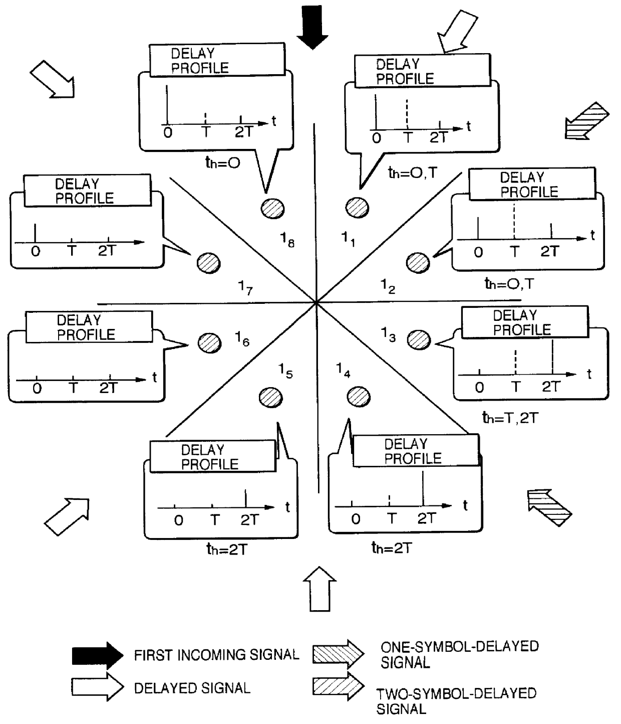
As shown in FIG. 6, each of elements 1.sub.1 to 1.sub.4 of the adaptive antenna according to the fourth embodiment can generate three beams P.sub.11, P.sub.12, . . . , P.sub.43 with different directivity. It is assumed that a first incoming signal, a one-symbol-delayed signal, and a two-symbol-delayed signal are received as shown in FIG. 6. In addition, it is assumed that delay profile estimating units (not shown) of the antenna elements estimate powers of received signals.
In the adaptive antenna according to the fourth embodiment, K (.ltoreq.4) antenna elements with larger power, intensity, or signal-to-noise ratio of a received signal of each of the first incoming signal, one-symbol-delayed signal, and two-symbol-delayed signal are selected from antenna elements that generate o...
PUM
 Abstract
Description
Claims
Application Information