Stripline coupling structure for high power HTS filters of the split resonator type

Inactive Publication Date: 2000-05-23
NIKON CORP +1
View PDF6 Cites 20 Cited by
  • Summary
  • Abstract
  • Description
  • Claims
  • Application Information

AI Technical Summary

Problems solved by technology

However, to obtain desired I / O coupling, the end coupling structure described in the co-pending application requires a very small gap, which can cause arcing.

Method used


Image

  • Stripline coupling structure for high power HTS filters of the split resonator type
  • Stripline coupling structure for high power HTS filters of the split resonator type
  • Stripline coupling structure for high power HTS filters of the split resonator type

Examples


Embodiment Construction

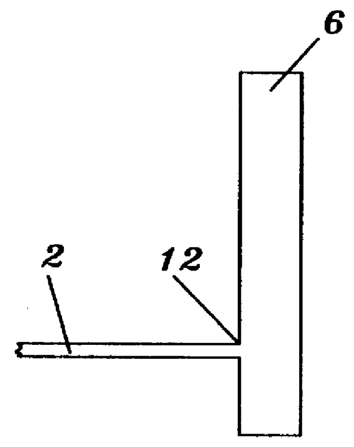
A resonator which is interfaced by an I / O coupling can be of a sliced resonator type. The feed line is inserted into the resonator in one of resonator gaps as shown in FIG. 6. By adjusting the depth of penetration and spacing between the feed line and resonator, a wide range of coupling values can be achieved. Since it is a smooth line configuration, no high current concentration exists due to discontinuities. The possibility of arcing is significantly reduced because of much wider spacing between the inserted line and resonator than with previous devices.

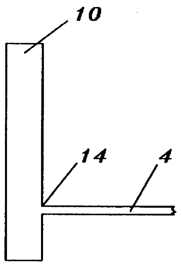
In FIG. 1, a prior art microstrip filter has feed lines 2, 4. There are three resonators 6, 8 and 10. Feed line 2 is in direct contact at point 12 to resonator 6. Feed line 4 is in direct contact at point 14 to resonator 10.

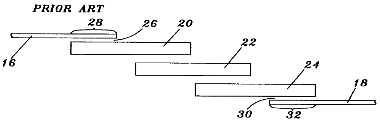
In FIG. 2, a prior art microstrip filter is shown with feed lines 16, 18 and resonators 20, 22 and 24. A gap 26 separates parallel section 28 of the feed line 16 from the resonator 20. Similarly, a gap 30 separa...


PUM

PropertyMeasurementUnit
temperatureaaaaaaaaaa
lengthaaaaaaaaaa
widthaaaaaaaaaa

Abstract

A microwave filter has a plurality of resonators and at least one transmission line mounted on a substrate having a ground plane. The filter can have input and output couplings that are transmission lines formed on the substrate or it can have input and output probes. The resonators have one or more gaps extending entirely therethrough, the gaps splitting the resonators into two or more slices. The transmission lines extend into the gap to couple energy into or out of a resonator or between two adjacent resonators. The transmission lines can have tapered ends or can be located off center so that they are closer to one side of a gap than to another side.

Description

1. Field of the InventionThis invention relates to microwave filters and, more particularly, to coupling mechanisms between transmission lines and resonators to provide improved power handling capability for microstrip / stripline type bandpass filters that are realized using high temperature superconductive materials. Further, this invention relates to a new coupling mechanism between input / output lines and resonators and between two adjacent resonators.When resonators and transmission lines are referred to in this application, they can be either microstrip or stripline resonators and transmission lines.2. Description of the Prior ArtTypical microstrip bandpass filters consist of input / output couplings, or I / O couplings and resonators where an I / O coupling consists of a feed line and an interface structure that provides a path from the feed line to the filter resonators. I / O couplings are also referred to as input / output terminations. An I / O coupling may be in the form of direct cont...

Claims


Application Information

Patent Timeline
Patent Type & Authority Patents(United States)
IPC IPC(8): H01P1/20H01P1/203
CPCH01P1/20363Y10S505/701Y10S505/866Y10S505/70
Inventor YE, SHENMANSOUR, RAAFAT R.
Owner NIKON CORP
Why Eureka
Try Eureka