Thermoelectric apparatus

a technology of thermoelectric apparatus and thermoelectric motor, which is applied in the direction of lighting and heating apparatus, machines using electric/magnetic effects, refrigerating machines, etc., can solve the problems of low thermal conductivity of plastic screws, low mechanical strength, and additional reinforcemen

Inactive Publication Date: 2000-06-13
FUJITAKA
View PDF4 Cites 67 Cited by
  • Summary
  • Abstract
  • Description
  • Claims
  • Application Information

AI Technical Summary

Problems solved by technology

On the other hand, plastic screws have low thermal conductivity but due to low mechanical strength, require additional reinforcement by an adhesive or the like.
Since the group of thermoelectric elements is fixed in place by fastening the thermal conductors together with the plural screws in the conventional thermoelectric apparatus as described above, it is difficult to apply uniform pressure to the group of thermoelectric elements.
Some of the thermoelectric elements are therefore subjected to localized load, so that they may be bro

Method used


Image

  • Thermoelectric apparatus
  • Thermoelectric apparatus
  • Thermoelectric apparatus

Examples


first embodiment

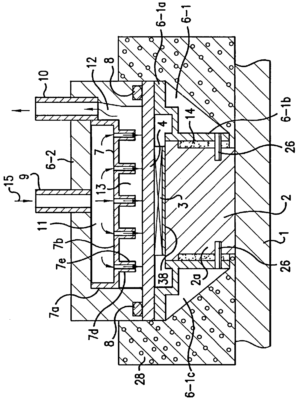
The thermoelectric apparatus according to the present invention will first be described with reference to FIGS. 1 to 3.

As is illustrated in FIG. 1, the thermoelectric apparatus is composed principally of a heat-absorbing member 1 arranged on a cooled side, for example, one a side of an interior of a refrigerator or the like, a heat-absorbing-side heat-exchanging base 2, a group thermoelectric elements 3, a heat-dissipating-side heat-exchanging base 4, a first heat-dissipating-side frame 6-1, a second heat-dissipating-side frame 6-2, and a distributing member 7.

The heat-absorbing member 1 is formed of a fin base having a wide area and is provided with a number of heat-absorbing fins (not shown). A fan may be arranged in a vicinity of the heat-absorbing member 1 as needed. Further, the fin base may be integrated with the heat-absorbing fins or may be arranged without them.

The heat-absorbing-side heat-exchanging base 2 and the heat-dissipating-side heat-exchanging base 4 are both made ...

second embodiment

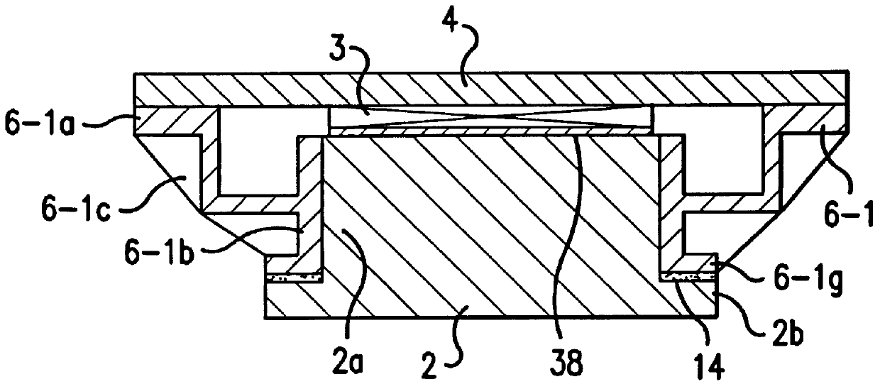
Referring next to FIG. 4, the thermoelectric apparatus according to the present invention will be described.

In this embodiment, an extended portion 2a of a heat-absorbing-side heat-exchanging base 2 is formed into a horizontally-extending outer flange portion 2b. On the other hand, an extended portion 6-1b of a first heat-dissipating-side frame 6-1 is also formed at a lower part thereof into an outer flange portion 6-1g. An adhesive layer 14 is interposed between both the outer flange portions 2b and 6-1g, so that the extended portion 2a of the heat-absorbing-side heat-exchanging base 2 and the extended portion 6-1b of the first heat-dissipating-side fame 6-1 are integrally joined together.

The adhesive layer 14 is arranged substantially in parallel with the extended portion 2a in the above-described first embodiment and is disposed substantially at a right angle relative to the extended portion 2a in the second embodiment. The extended portions 2a, 6-1b can be modified in shape so t...

third embodiment

The thermoelectric apparatus according to the present invention will be described with reference to FIG. 5.

The thermoelectric apparatus is composed principally of a heat-absorbing member 1 to be arranged on a cooled side, a heat-absorbing-side heat-exchanging base 2, a group of thermoelectric elements 3, a heat-dissipating-side heat-exchanging base 4, a heat-absorbing-side frame 5, a heat-dissipating-side frame 6, and a distributing member 7.

The heat-absorbing-side frame 5 is in the form of a hollow shape open through top and bottom parts thereof, has a basal end portion 5a and an extended portion 5b extending upwardly from an inner peripheral portion of the basal portion 5a, and has a substantially L-shaped cross-section. Formed in a lower surface of the basal end portion 5a is a groove in which an O-ring 8 is received, whereby the lower surface of the basal end portion 5a is joined in a liquid-tight fashion to a peripheral portion of the heat-absorbing-side heat-exchanging base 2....


PUM


Abstract

A thermoelectric apparatus is composed of a heat-absorbing-side heat-exchanging base and a heat-dissipating-side heat-exchanging base having good thermal conductivity and arranged in a mutually opposing relationship with a group of thermoelectric elements interposed therebetween. The thermoelectric apparatus comprises a frame made of a synthetic resin material and holding one of the heat-absorbing-side heat-exchanging base and the heat-dissipating-side heat-exchanging base at an outer peripheral portion thereof. The frame and the other heat-exchanging base, which is not held by the frame, are both provided with extended portions extending substantially along and substantially in the same direction as a stacked direction of the heat-absorbing-side heat-exchanging base, the group of thermoelectric elements and the heat-dissipating-side heat-exchanging base. The extended portions are joined together.

Description

a) Field of the InventionThis invention relates to a thermoelectric apparatus such as a thermoelectric cooling apparatus or a thermoionic electricity generator, and especially to a thermoelectric apparatus which does not undergo much performance degradation even through repeated heat cycles and has excellent operation reliability and long service life.b) Description of the Related ArtIn a conventional thermoelectric apparatus, a group of thermoelectric elements is arranged between thermal conductors, and is fixed in place by fastening the thermal conductors together with plural screws with a thermally-conductive grease applied between each thermal conductor and the group of thermoelectric elements to improve their thermal contact.As the screws, those made of metal or plastics are used. Metal screws have sufficient strength for the fixing of the group of thermoelectric elements. These metal screws are used in combination of heat-insulating washers because their thermal conductivity i...

Claims


Application Information

Patent Timeline
IPC IPC(8): H01L35/32H01L35/28H01L35/30F25B21/02
CPCH01L35/32H01L35/30F25B2321/023H10N10/17H10N10/13
Inventor WATANABE, HIDEOTEZUKA, HIROFUSAOGASAWARA, MITSUTOSHISUZUKI, NOBUHIKOSATO, KAZUYA
Owner FUJITAKA
Why Eureka
Try Eureka