

Piezoelectric glide head
- Summary
- Abstract
- Description
- Claims
- Application Information
AI Technical Summary
Benefits of technology
Problems solved by technology
Method used
Image

Examples
Embodiment Construction
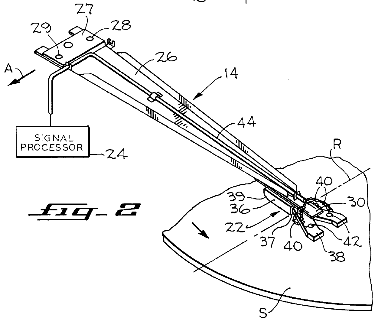
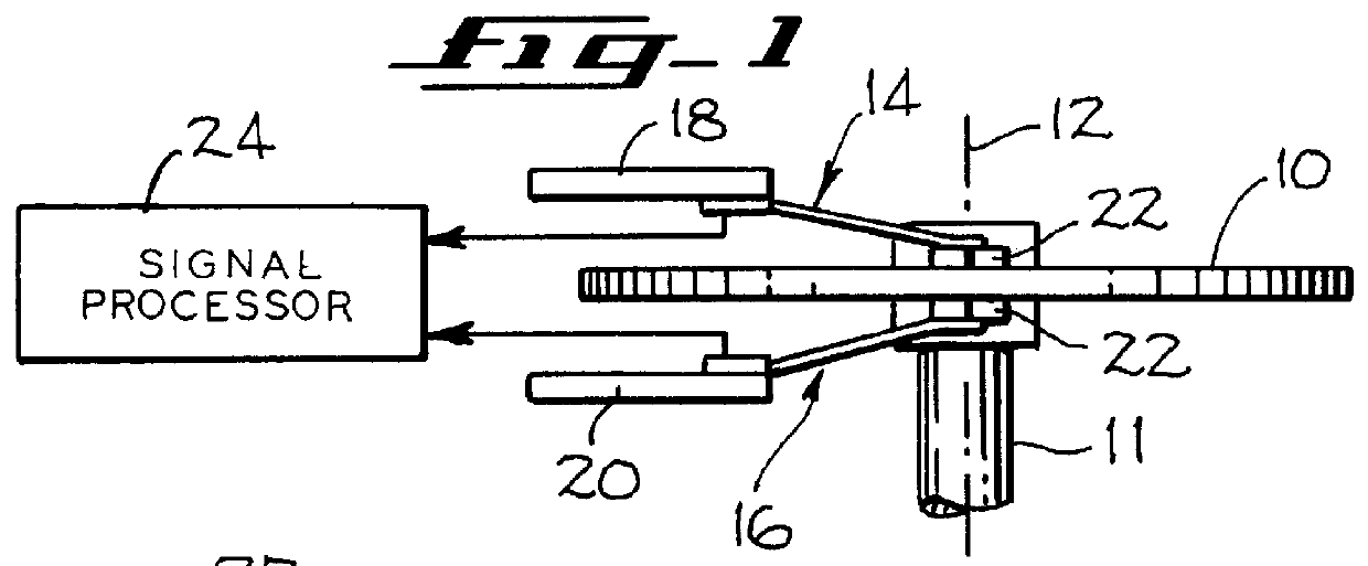
FIG. 1 shows diagrammatically the novel glide head 22 of the present invention in a more or less conventional glide head arrangement for testing for asperities or anomalies on the opposed surfaces of a flat magnetic recording disk 10. The recording disk is appropriately fixed upon an upright spindle 11 and is adapted to be rotated by the spindle (by means not shown) about a vertical axis 12 where its upper surface can be tested by a glide head assembly 14 and its lower surface can be tested by a glide head assembly 16. Each of the glide head assemblies 14 and 16 is secured to a driver mechanism 18, 20, respectively, so that they may be moved in the radial direction of the disk 10, and each of the glide head assemblies 14, 16 includes the glide head 22 at its distal, or projecting, end which includes a sensing edge adapted to ride on an air bearing at a very close spacing to the disk 10 surface when the disk 10 is rotated at a sufficient rotational speed. The glide head assemblies fu...
PUM
 Abstract
Description
Claims
Application Information