Multiple-feed electromagnetic signal receiving apparatus

a multi-feed, electromagnetic signal technology, applied in the direction of electrical equipment, antenna details, antennas, etc., can solve the problems of excessive spill over loss, difficult to place two conventional horn feeds within the required distance, and too expensive antennas for general home us

Inactive Publication Date: 2000-06-13
ACER INC
View PDF17 Cites 24 Cited by
  • Summary
  • Abstract
  • Description
  • Claims
  • Application Information

AI Technical Summary

Problems solved by technology

However, employing these methods would make the antenna too expensive for general home use.
With an F/D (dish focal length over dish diameter) ratio fixed, as the dish size is decreased to less than half a meter, it becomes very difficult to place two conventional horn feeds within the re

Method used


Image

  • Multiple-feed electromagnetic signal receiving apparatus
  • Multiple-feed electromagnetic signal receiving apparatus
  • Multiple-feed electromagnetic signal receiving apparatus

Examples


Embodiment Construction

The present invention is a multi-feed signal receiver for receiving signals from two satellites (or two satellite clusters). The signal receiver comprises signal feeds for feeding signals to a circuit module for processing of the signals. For clarity of description, an LNBF (Low Noise Block with integrated Feed) is used as an illustration of an embodiment. The term LNBF is used for purposes of illustration only, and does not limit the scope of the present invention.

In the following description, for simplicity, whenever convenient, similar components will have the same numbering labels regardless of embodiment.

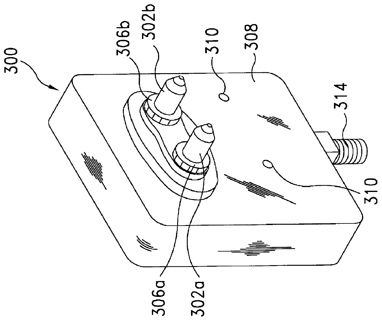
As shown in FIG. 2, a twin rod LNBF 300 comprises an outer housing 308, two chokes 306a and 306b, two rod feeds 302a and 302b, and a coupling port 314 for coupling output signals to a tuner device (not shown in the figure). The two chokes 306a, 306b are attached to the housing 308, and the two rod feeds 302a and 302b protrude from the two chokes 306a and 306b.

The protruding rod...


PUM


Abstract

This invention discloses a novel design for receiving electromagnetic signals broadcasted from at least two of satellite clusters and collected by a single dish antenna. At least two signal feeds are used to feed the signals to a processing circuit. The processing circuit performs signal selection, amplification, and frequency conversion. Corrective lens are used to ensure uniform wavefront of the electromagnetic signals received by the signal feeds located farther away from the focal point of the dish antenna. A convenient adjustment device is provided for adjustment of the relative positions of the signals feeds to the dish antenna.

Description

1. Field of the InventionThis invention relates generally to electromagnetic signal receiving devices, and more particularly to a receiving antenna with a plurality of feeds for receiving microwave signals emanating from more than one direction.2. Description of the Prior ArtDirect Broadcast Satellite (DBS) is a point-tom-ultipoint system in which individual households equipped with a small receiving antenna and tuner device receive broadcasts directly from a geostationary satellite. The satellite receives digital audio and video transmissions from ground stations and relays them directly to individuals. The receiving antenna is comprised of a parabolic dish designed to collimate the satellite signals at the focal point, where an LNBF (Low Noise Block with integrated Feed) module is mounted to convert the incoming signals to a lower frequency band and transmit it to a tuner device. The LNBF module also acts as a filter and an amplifier to selectively boost the signal received by the...

Claims


Application Information

Patent Timeline
IPC IPC(8): H01Q19/12H01Q19/17H01Q25/00H01Q19/10H01Q19/00H01Q1/24H01Q19/06
CPCH01Q1/247H01Q19/062H01Q25/00H01Q19/17H01Q19/175H01Q19/12
Inventor CHEN, MICHAELGAU, JIAHN-RONG
Owner ACER INC
Why Eureka
Try Eureka