Blind fastener with high strength blind head and high clamp and high shear load resistance

a blind head and fastener technology, applied in the direction of fastening means, screws, dowels, etc., can solve the problems of uneven axial load to be applied to the installed fastener, not necessarily increasing the clamp load, and routinely being a resultant tensile load componen

Inactive Publication Date: 2000-06-20
HUCK INT INC
View PDF110 Cites 45 Cited by
  • Summary
  • Abstract
  • Description
  • Claims
  • Application Information

AI Technical Summary

Problems solved by technology

The extra load to provide pin break, however, does not necessarily increase the clamp load.
When such lap shear loads are applied to a fastener, however, there routinely is a component of resultant tensile load applied to the fastener as well.
It is believed that this is caused to some extent by the fact that since the workpieces are axially offset the shear loads as applied to the workpieces in opposite transverse directions, will result in some degree of bending or twisting which will cause an uneven axial load to be applied to the installed fastener.
However, the uneven tensile loads or forc

Method used


Image

  • Blind fastener with high strength blind head and high clamp and high shear load resistance
  • Blind fastener with high strength blind head and high clamp and high shear load resistance
  • Blind fastener with high strength blind head and high clamp and high shear load resistance

Examples


Embodiment Construction

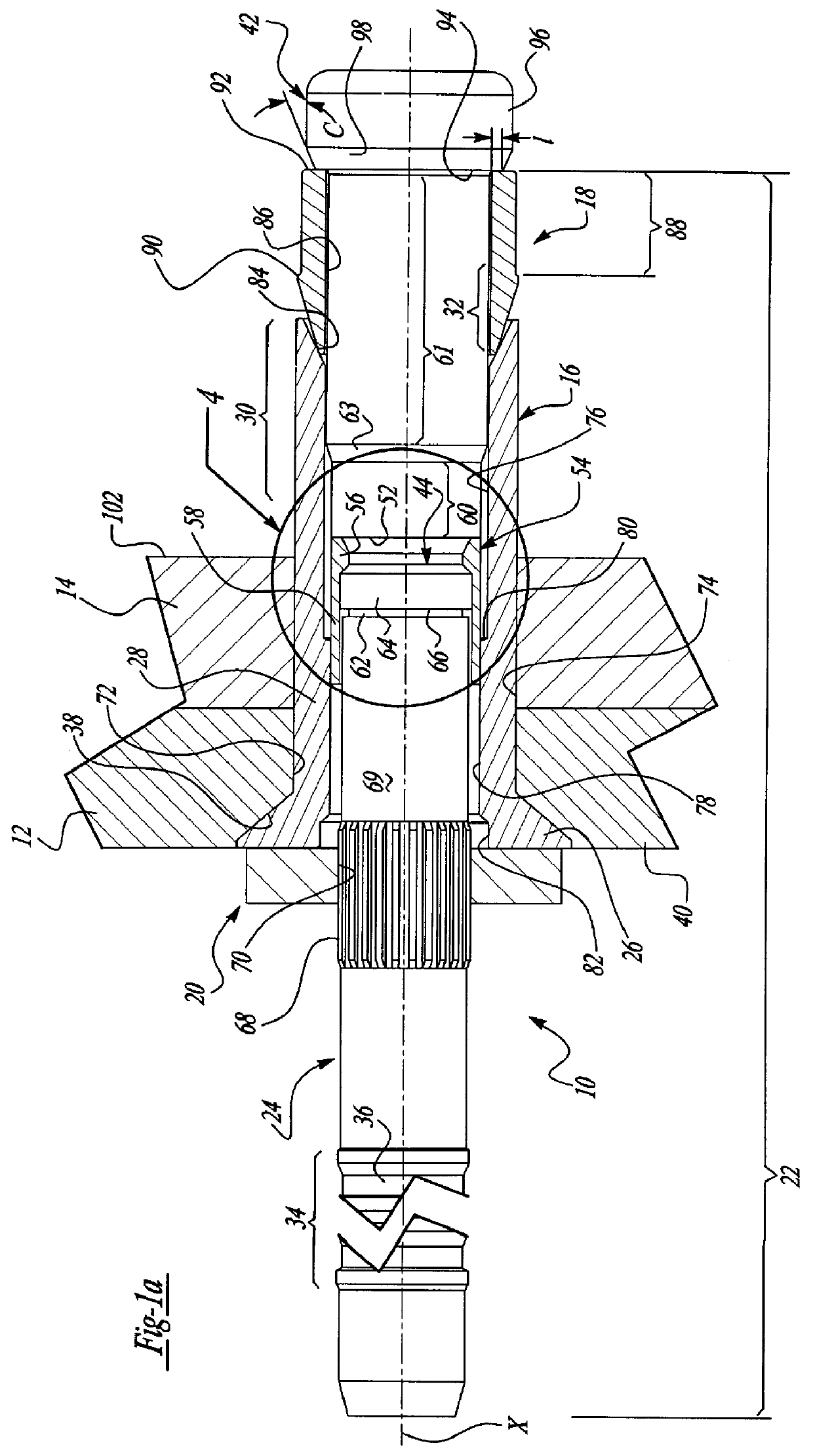
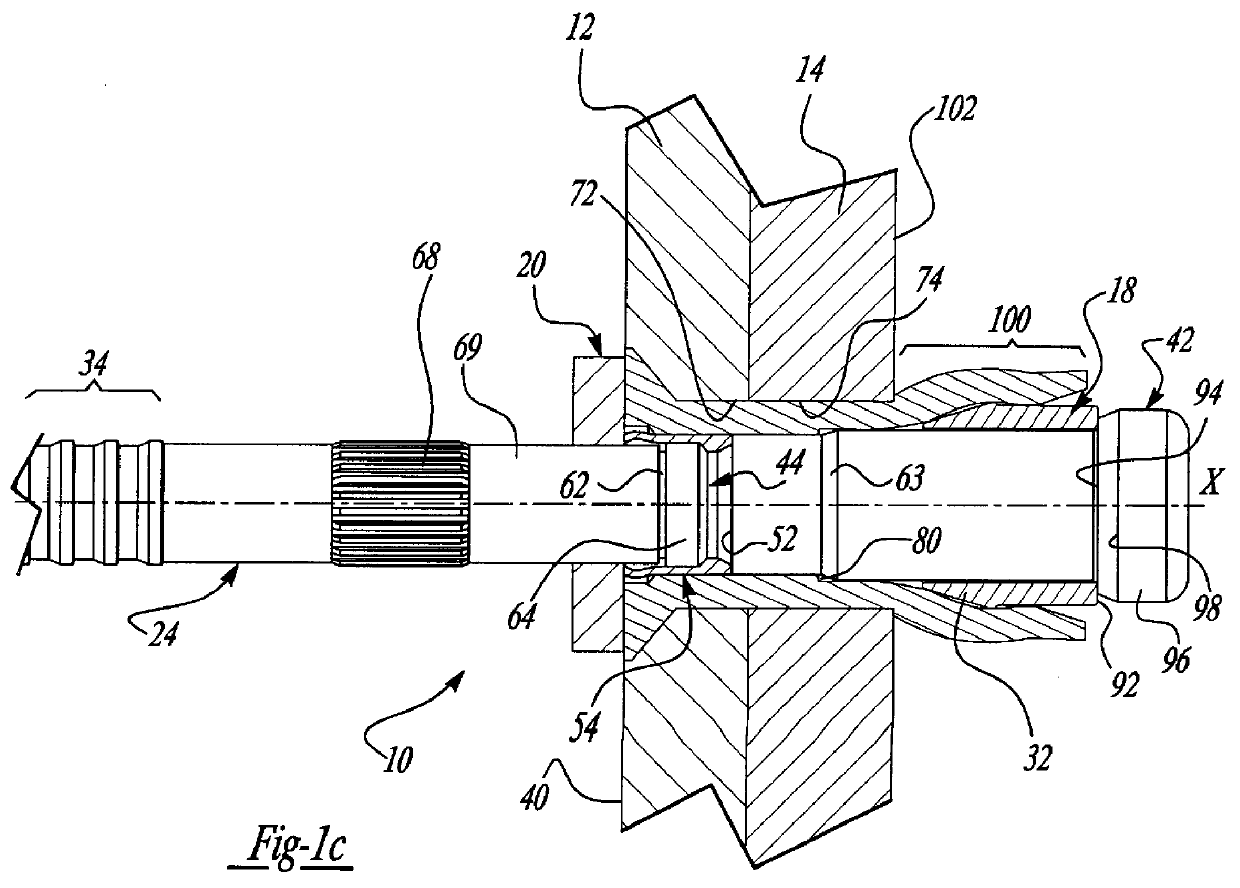
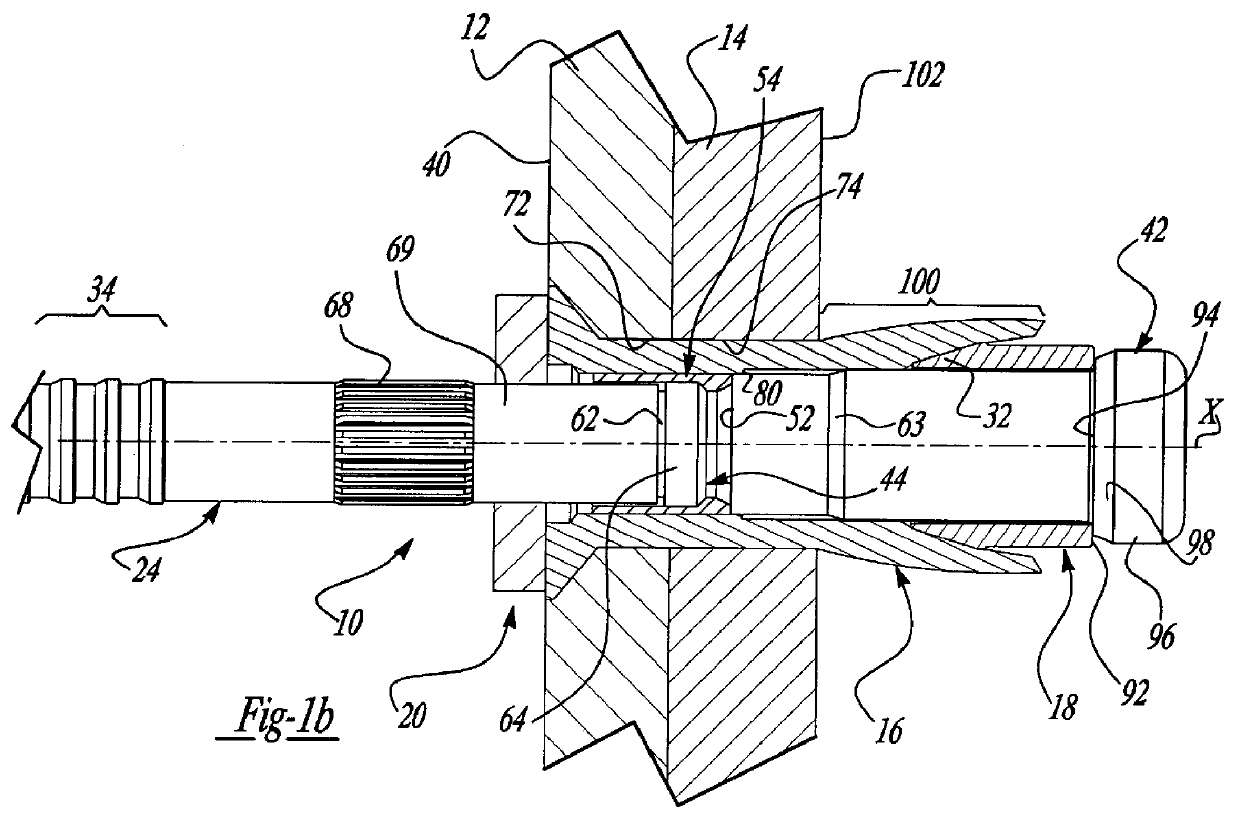
The fastener 10 as shown in FIG. 1a is adapted to secure together outer and inner workpieces 12 and 14, respectively, and consists of a main sleeve 16, an expander sleeve 18 and an anvil washer 20 all supported upon the shank 22 of a pin member 24. The main sleeve 16 is of a tubular form and has an enlarged head 26 on the outer end of a cylindrical sleeve shank 28. The cylindrical shank 28 terminates at its inner or blind side end in a radially expandable, blind head section 30. The expander sleeve 18 is of a cylindrical form and has a tapered expansion section 32 which as will be seen is adapted to engage the blind head section 30 of the main sleeve 16 to form a blind head. The details of the main sleeve 16 and expander sleeve 18 can best be seen in FIGS. 2 and 3, respectively.

As can be seen in FIG. 1a, the elongated shank 22 of pin member 24 extends through the main sleeve 16 and expander sleeve 18. The pin shank 22 has a pulling portion 34 at its outer end, which is provided with...


PUM

PropertyMeasurementUnit
Forceaaaaaaaaaa
Lengthaaaaaaaaaa
Thicknessaaaaaaaaaa

Abstract

A blind fastener with a pin having a pin shank which extends through a cylindrical main sleeve and expansion sleeve whereby it can be gripped and pulled by an installation tool with the pin having an enlarged pin head at the blind end of the pin shank. The expansion sleeve is located between the pin head and the inner end of the main sleeve and is adapted to move into the inner or blind end of the main sleeve to form a first tulip shaped blind head for clamping workpieces together in response to a relative axial force applied between the sleeves and pin by engagement of the pin head with the expansion sleeve. As the axial force is increased the pin head is moved into the expansion sleeve to form a second tulip head to further clamp the workpieces and to secure the pin, main sleeve and expansion sleeve together at that end and is moved closely adjacent the workpiece surface at the blind side to form a high strength blind head.

Description

SUMMARY BACKGROUND OF THE INVENTIONThe present invention relates to a blind fastener wherein a main sleeve and expander sleeve are assembled onto a pin shank of a pin member having an enlarged pin head with the expander sleeve at the blind end in engagement with the pin head such that as a relative axial force is applied between the pin and the sleeves the expander sleeve is moved into the adjacent end of the main sleeve to expand that end radially outwardly to form a first tulip shaped blind head and with the pin head then moving into the expander sleeve to form a second tulip shaped blind head.In securing workpieces together with a blind fastener it is desirable to be able to attain a high final clamp load on the workpieces. At the same time it is also desirable that the installed fastener have the capability of withstanding high shear loads. The magnitude of clamp load is established by the relative axial force applied between the pin and a sleeve structure essentially when the b...

Claims


Application Information

Patent Timeline
IPC IPC(8): B21J15/00B21J15/06B21J15/04F16B19/04F16B19/10F16B13/06F16B13/12
CPCB21J15/043F16B19/1054B21J15/045F16B13/04
Inventor HAZELMAN, DAVID J.
Owner HUCK INT INC
Why Eureka
Try Eureka