Spatially switched achromatic compound retarder

a technology of achromatic retarders and achromatic compounds, which is applied in the field of compound retarders, can solve the problems of limited spectral operating range of birefringent optical devices, limited chromaticity, and inability to achieve chromaticity,

Inactive Publication Date: 2000-06-20
REAID INC
View PDF19 Cites 40 Cited by
  • Summary
  • Abstract
  • Description
  • Claims
  • Application Information

AI Technical Summary

Problems solved by technology

Chromaticity places limitations on the spectral operating range of birefringent optical devices.
Because these design equations specify a unique orientation of the central retarder and a unique retardance for the external retarders, they have never been applied to active liquid crystal devices and the problem of active retarder chromaticity remains.
High transmission through FLC shutters over broad wavelength bands is feasible for devices of zero-order retardance, but it is ultimately limited by the inverse-wavelength dependence of retardation and the rather large birefringence dispersion of liquid crystal materials.
This significantly limits the brightness of FLC displays and the operating band of FLC shutters and light modulators.
In systems incorporating multiple FLC devices, such as tunable optical filters or field-sequential display color shutters, this source of light loss can have a devastating impact on overall throughput and spectral purity.

Method used


Image

  • Spatially switched achromatic compound retarder
  • Spatially switched achromatic compound retarder
  • Spatially switched achromatic compound retarder

Examples


first embodiment

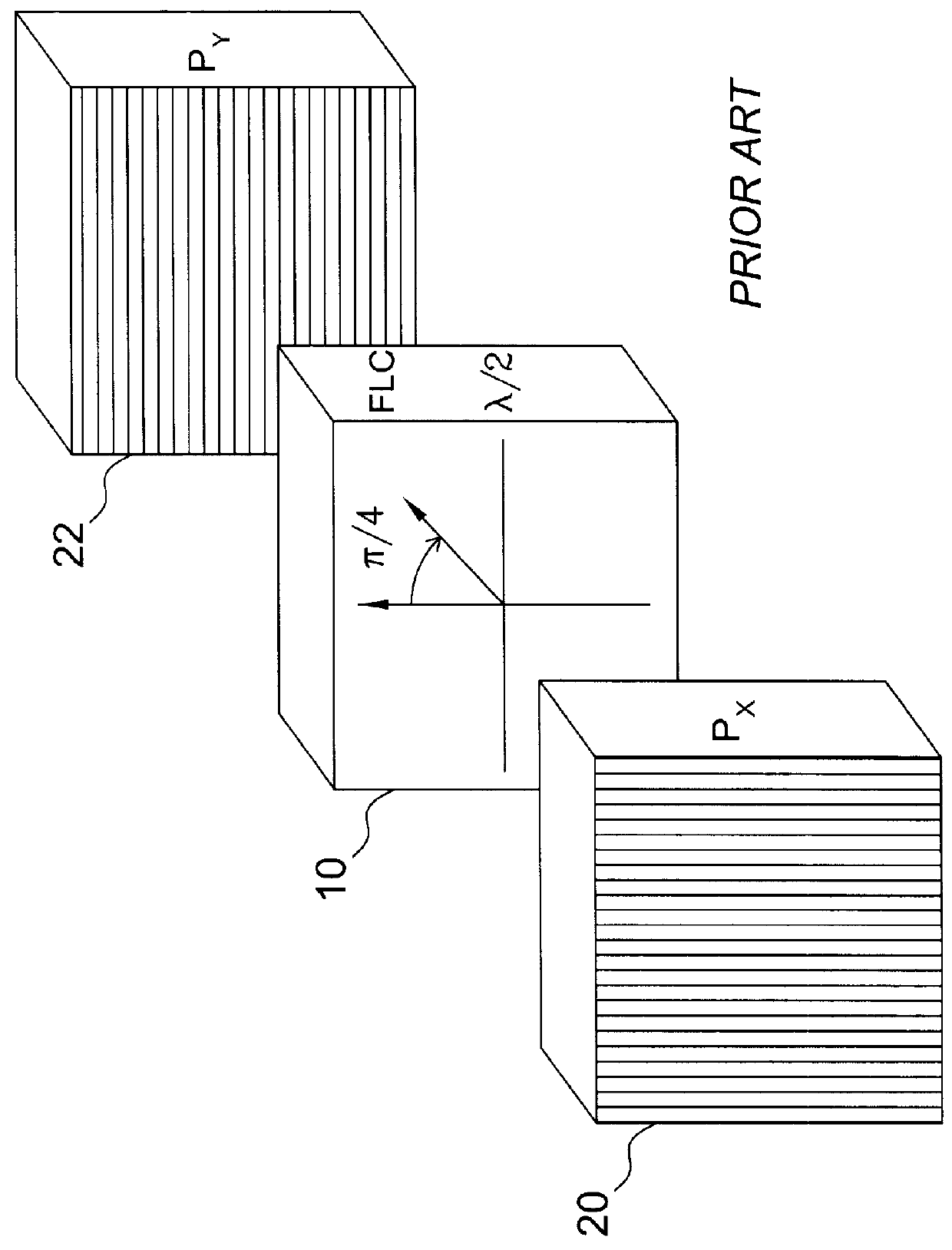
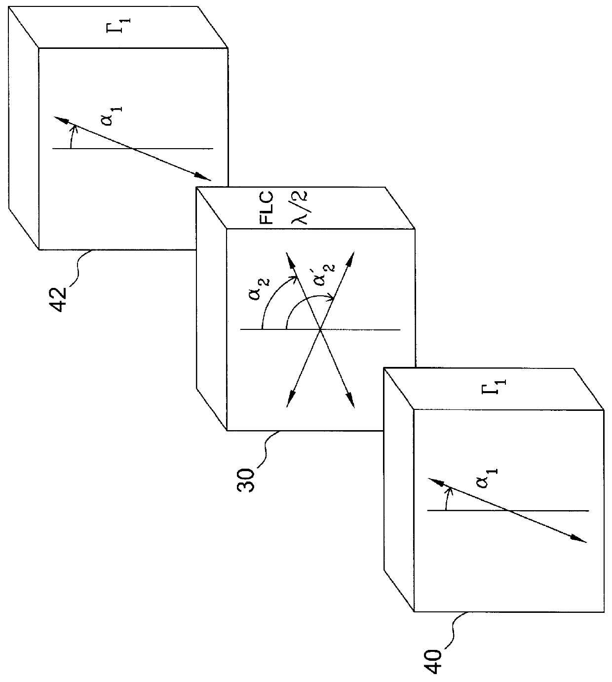
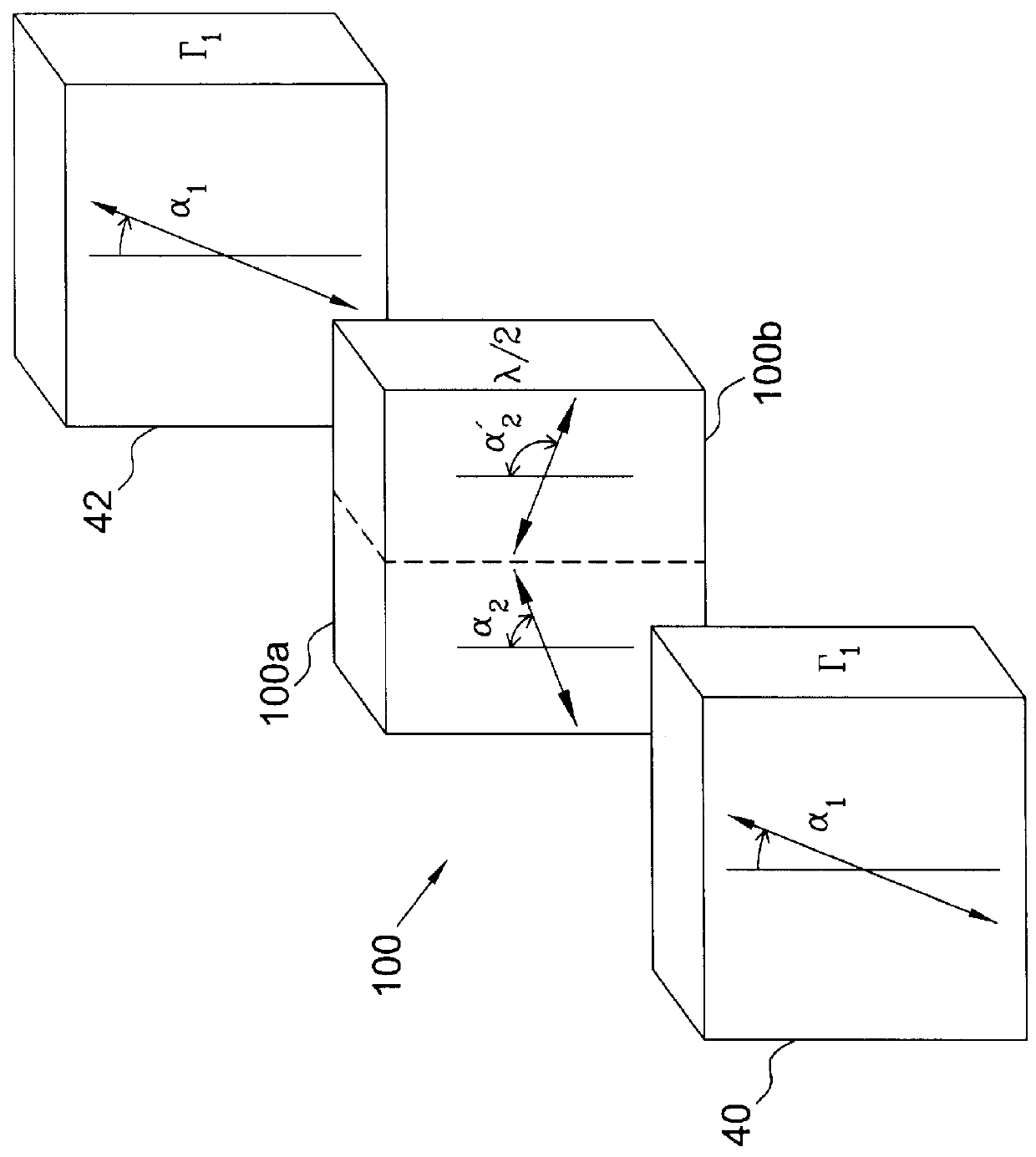
the achromatic compound retarder of this invention (FIG. 2a) comprises planar-aligned smectic liquid crystal retarder 30 having an orientation which is electronically rotatable between angles .alpha..sub.2 and .alpha..sub.2 '. These orientations are herein termed the on-state and the off-state, respectively. Retarder 30 provides a half-wave retardance (.GAMMA..sub.2.sup.0 =.pi.) at the design wavelength. Outer retarders 40 and 42, with orientation (and retardance .GAMMA..sub.1.sup.0 at the design wavelength, are positioned on either side of central retarder 30. In an alternative embodiment, the outer retarders 40 and 42 are crossed instead of parallel. In this application the design equations are derived for the case of parallel retarders. Analogous equations can be derived for crossed retarders.

In this embodiment, the central retarder is an FLC, but it can be any material with an electronically rotatable optic axis, including planar aligned SmC* and SmA* liquid crystals, as well as...


PUM

PropertyMeasurementUnit
thicknessaaaaaaaaaa
γaaaaaaaaaa
wavelengthaaaaaaaaaa

Abstract

This invention provides achromatic compound retarders, achromatic polarization switches, and achromatic shutters using the liquid crystal compound retarders. It further provides achromatic variable retardance smectic liquid crystal retarders. The achromatic compound retarder of this invention comprises a central liquid crystal retarder unit and two outer retarders positioned in series with and on either side of the liquid crystal retarder unit. The liquid crystal retarder unit comprises either (1) a rotatable smectic liquid crystal half-wave retarder or (2) first and second liquid crystal variable retarders having retardance switchable between zero and half-wave. The outer retarders have substantially the same retardance and orientation. Design equations determine the retardance of the outer retarders and their orientation relative to the central retarder to obtain a particular achromatic retardance for the compound structure.

Description

BACKGROUND OF THE INVENTION1. Field of the InventionThe present invention relates generally to compound retarders. More specifically, the present invention is directed to achromatic compound retarders that exhibit an achromatic composite optic axis orientation and / or an achromatic composite compound retardance at each of at least two composite retarder orientation states.2. Background of the Related ArtLiquid crystal retarders are increasingly utilized within optical devices such as tunable filters, amplitude modulators and light shutters. Planar aligned smectic liquid crystal devices function as rotative waveplates wherein application of an electric field rotates the orientation of the optic axis but does not vary the birefringence. In contrast, homeotropically aligned smectic liquid crystals, homogeneous aligned nematic devices, and nematic .pi.-cells function as variable retarders, wherein application of an electric field varies the birefringence. Chromaticity is a property of bi...

Claims


Application Information

Patent Timeline
Patent Type & Authority Patents(United States)
IPC IPC(8): C09K19/52G02F1/13G02F1/1335
CPCG02F1/1335C09K19/52G02B5/3083G02F1/13363G02B5/3016G02F1/133638G02F1/133633G02B27/288
Inventor SHARP, GARY D.JOHNSON, KRISTINA M.
Owner REAID INC
Why Eureka
Try Eureka