Actuator for an aircraft flight control surface

a technology for aircraft flight control and actuators, applied in the field of actuators, can solve the problems of limited life of motors, actuators that do not provide sufficient amplitudes for primary flight control, and hydraulics are too large to achieve the effect of long li

Inactive Publication Date: 2000-07-04
SAGEM SA
View PDF9 Cites 18 Cited by
  • Summary
  • Abstract
  • Description
  • Claims
  • Application Information

AI Technical Summary

Benefits of technology

With such an actuator, the advantages of vibration motors which enable large-amplitude movements to be perf

Problems solved by technology

However, for various reasons (maintenance, pollution, fire risk, etc. . . . ), aircraft manufacturers are seeking to reduce the amount of hydraulics in control systems in favor of electrical controls.
Nevertheless, with this type of motor, continu

Method used


Image

  • Actuator for an aircraft flight control surface
  • Actuator for an aircraft flight control surface
  • Actuator for an aircraft flight control surface

Examples


Embodiment Construction

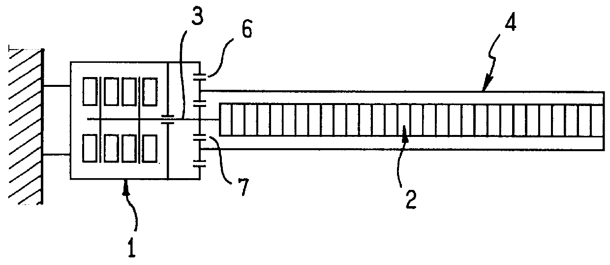
The actuator shown in FIG. 1 comprises firstly a motor 1 which is of the vibration type and makes large-amplitude movements possible, and secondly a motor 2 which is a piezoelectric, electrostrictive, or magnetostrictive actuator of the direct type and which provides movements of small amplitude.

These two motors 1 and 2 are mounted in series. More particularly, the motor 2 is mounted on a shaft 3 driven by the motor 1. The motor 2 itself drives an attachment structure 4 on which the control surface actuated by said motors 1 and 2 is mounted.

By way of example, the vibration motor 1 is of the type described in the Applicants' French patent application published under the No. 2 742 011 or in their French patent application filed under the No. 97 / 10948.

By way of example, the motor 2 is an amplified actuator of the type described in:

"A new amplifier piezoelectric actuator for precise positioning and semi-passive damping", R. Le Letty, F. Claeyssen, G. Thomin, 2nd Space Microdynamics and ...


PUM


Abstract

An actuator for a primary control surface of an air-craft, the actuator comprising at least one motor of the vibration type mounted in series with at least a second motor which is a piezoelectric, electrostrictive, or magnetostrictive actuator of the direct type, and further including control means causing one or both of the motors to operate in such a manner that the second motor drives movements of the control surface of the type used for stabilizing the aircraft, while the vibration drives movements of greater amplitude.

Description

The present invention relates to actuators for air-craft flight control surfaces.Two types of flight control exist on board aircraft:primary controls which serve to control immediate movements; on an airplane these are generally flat surfaces situated in the trailing edges of the wings;secondary flight controls which serve to adjust the aerodynamic configuration of the aircraft to various stages of flight; this category includes wing slats and landing flaps and the rear tail plane.In general, primary and secondary flight controls are implemented using hydraulic devices.However, for various reasons (maintenance, pollution, fire risk, etc. . . . ), aircraft manufacturers are seeking to reduce the amount of hydraulics in control systems in favor of electrical controls.An object of the invention is to propose a primary flight control of the electrical type.Proposals have already been made for secondary flight controls to implement actuators by means of "vibration" motors, in which tange...

Claims


Application Information

Patent Timeline
IPC IPC(8): B64C13/00B64C13/50H02K33/00H02N2/00
CPCB64C13/50
Inventor AUDREN, JEAN THIERRY
Owner SAGEM SA
Why Eureka
Try Eureka