Spar with improved VIV performance

Inactive Publication Date: 2000-07-25
SHELL OIL CO
View PDF35 Cites 71 Cited by
  • Summary
  • Abstract
  • Description
  • Claims
  • Application Information

AI Technical Summary

Benefits of technology

A present invention is a method for reducing VIV in a spar platform having a deck, a cylindrical hull having a buoyant tank assembly, a counterweight and an counte

Problems solved by technology

Efforts to economically develop offshore oil and gas fields in ever deeper water create many unique engineering challenges.
One of these challenges is providing a suitable surface accessible structure.
The typical single column profile of the hull is particularly susceptible to VIV problems in the presence of a passing cur

Method used


Image

  • Spar with improved VIV performance
  • Spar with improved VIV performance
  • Spar with improved VIV performance

Examples


Example

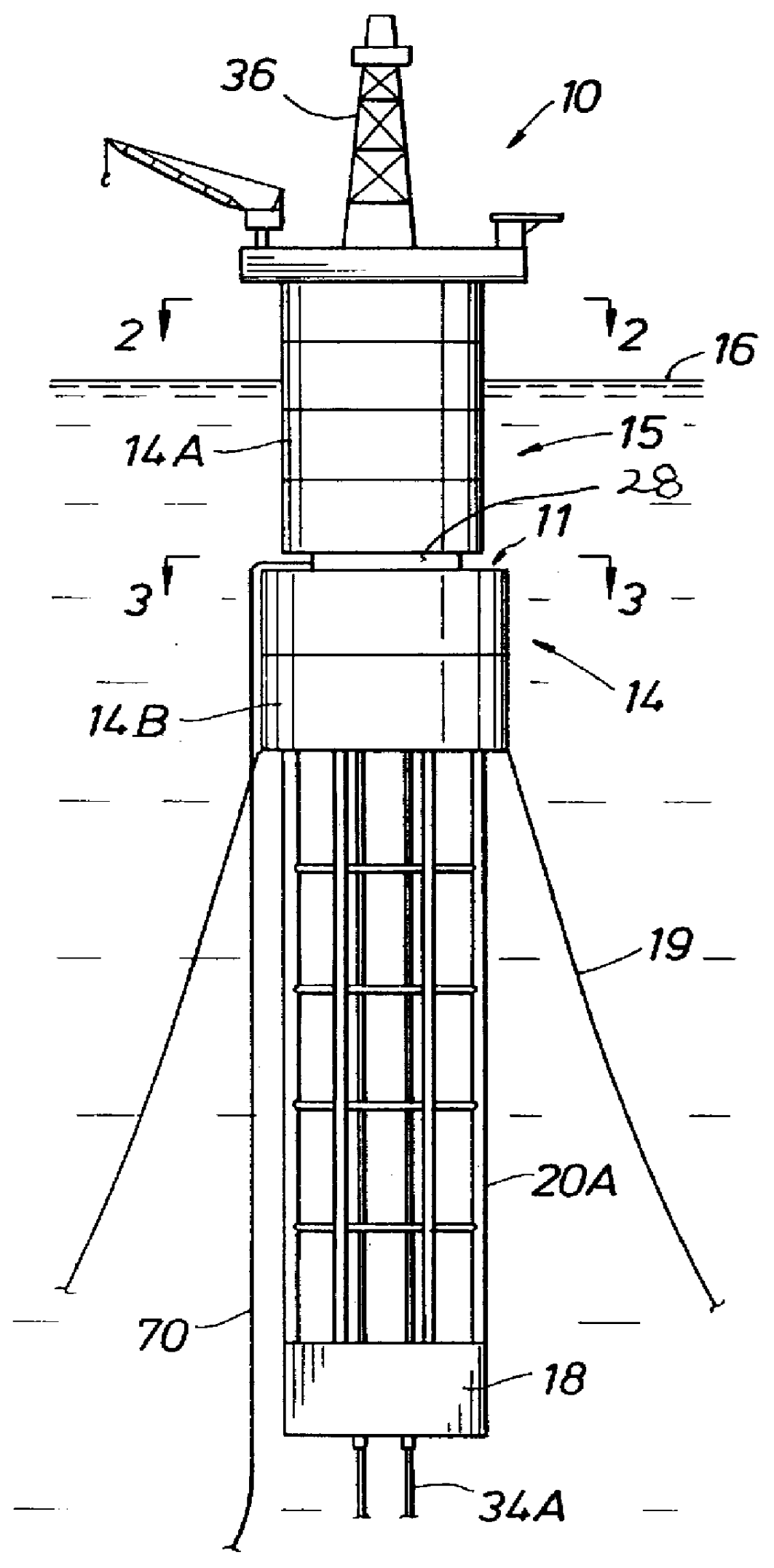
FIG. 1 illustrates a spar 10 in accordance with the present invention. Spars are a broad class of floating, moored offshore structure characterized in that they are resistant to heave motions and present an elongated, vertically oriented hull 14 which is buoyant at the top, here buoyant tank assembly 15, and is ballasted at its base, here counterweight 18, which is separated from the top through a middle or counterweight spacing structure 20.

Such spars may be deployed in a variety of sizes and configuration suited to their intended purpose ranging from drilling alone, drilling and production, or production alone. FIGS. 1-4 illustrate a drilling and production spar, but those skilled in the art may readily adapt appropriate spar configurations in accordance with the present invention for either drilling or production operations alone as well in the development of offshore hydrocarbon reserves.

In the illustrative example of FIGS. 1 and 2, spar 10 supports a deck 12 with a hull 14 havi...


PUM


Abstract

A method for reducing VIV is disclosed for a spar platform having a deck, a cylindrical hull having a buoyant tank assembly, a counterweight and an counterweight spacing structure. The overall aspect ratio of the hull is reduced by providing one or more abrupt changes in hull diameter below the waterline.

Description

The present invention relates to a heave resistant, deepwater platform supporting structure known as a "spar." More particularly, the present invention relates to reducing the susceptibility of spars to drag and vortex induced vibrations ("VIV").Efforts to economically develop offshore oil and gas fields in ever deeper water create many unique engineering challenges. One of these challenges is providing a suitable surface accessible structure. Spars provide a promising answer for meeting these challenges. Spar designs provide a heave resistant, floating structure characterized by an elongated, vertically disposed hull. Most often this hull is cylindrical, buoyant at the top and with ballast at the base. The hull is anchored to the ocean floor through risers, tethers, and / or mooring lines.Though resistant to heave, spars are not immune from the rigors of the offshore environment. The typical single column profile of the hull is particularly susceptible to VIV problems in the presence...

Claims


Application Information

Patent Timeline
IPC IPC(8): B63B39/00B63B1/04B63B35/44B63B1/00
CPCB63B1/048B63B35/4406B63B39/005B63B2001/044B63B2035/442
Inventor ALLEN, DONALD WAYNEHENNING, DEAN LEROYBALINT, STEPHEN W.MCMILLAN, DAVID WAYNE
Owner SHELL OIL CO
Why Eureka
Try Eureka