Sling load portal for cargo box

Inactive Publication Date: 2000-08-15
DEERE & CO
View PDF4 Cites 12 Cited by
  • Summary
  • Abstract
  • Description
  • Claims
  • Application Information

AI Technical Summary

Problems solved by technology

Sling loading a utility vehicle having a cargo box is particularly problematic because the cargo boxes of such vehicles are typically substantially larger than the frame of the utility vehicle itself, so that the lift provisions attached to the frame are located beneath th

Method used


Image

  • Sling load portal for cargo box
  • Sling load portal for cargo box
  • Sling load portal for cargo box

Examples


Embodiment Construction

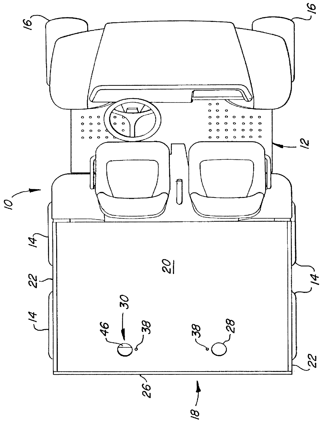
FIG. 1 shows a utility hauling vehicle 10 including a main frame 12 supported by four drive wheels 14 and a pair of steerable front wheels 16. Supported on the frame 12 in a location above the drive wheels 14 is a cargo box 18. The box 18 includes a horizontal floor or bed 20 and vertical right and left sidewalls 22, a front wall 24 and a tailgate 26. The tailgate 26 forms a rear wall of the box 18 and is mounted for selectively closing the opening defined by the rear edges of the bed 20 and the sidewalls 22. The sidewalls 22 are also mounted for pivoting about horizontal axes. In this manner, the sidewalls 22 and the tailgate 26 may be pivoted from closed, upright positions to open, recumbent positions wherein they effectively become extensions of the bed 20 and the cargo box 18 may be thereby converted to a flat bed (not shown). The bed 20 is provided with spaced-apart openings 28 associated with sling load portal assemblies 30.

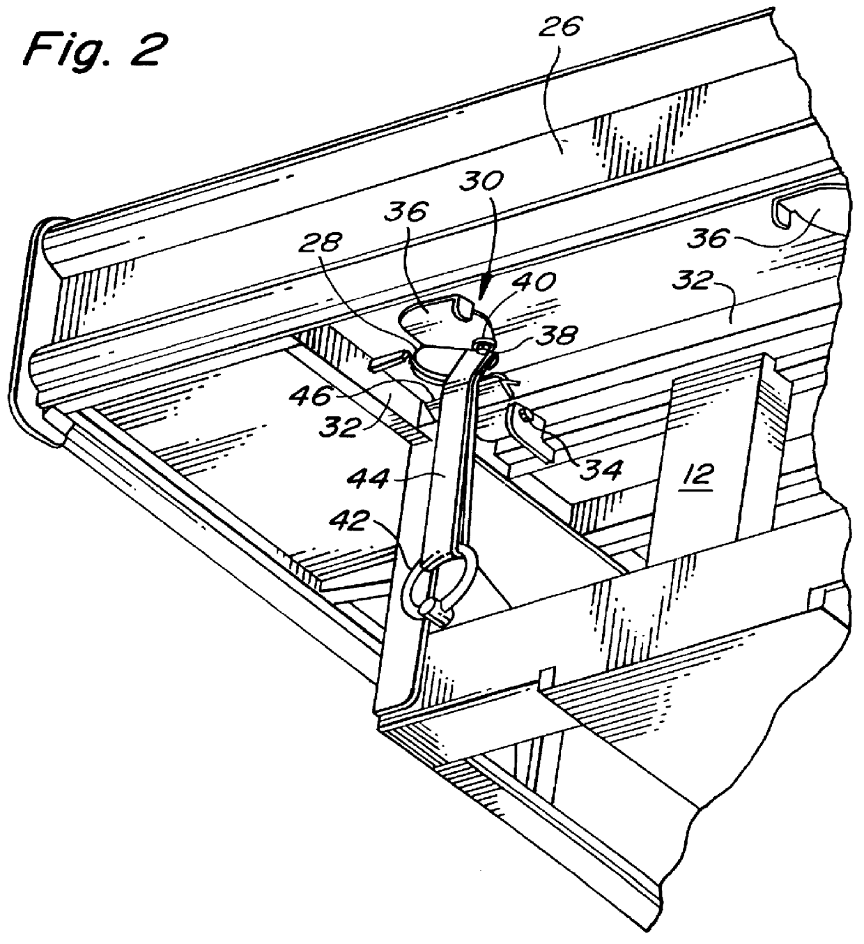
A rear worm's eye view of the vehicle 10 is shown in ...


PUM


Abstract

A vehicle includes a bed having an opening through which a sling leg may be passed. A sling load portal includes the opening and a door mounted under the bed and movable between a closed position wherein the door is in registration with the opening and an open position wherein the door is removed from registration with the opening, providing a path through the bed to a lift provision connected to the frame of the vehicle.

Description

1. Field of the InventionThe present invention relates to hauling vehicles having frame-mounted cargo boxes and more particularly relates to structure for sling loading of such vehicles. A preferred embodiment of the present invention relates to a sling load portal including a selectively sealable opening in the bed of the cargo box of a utility vehicle.2. Description of Related ArtVarious hauling vehicle designs are known which include a cargo box having side walls and a tailgate which forms a rear wall thereof.Utility vehicles such as the vehicle described herein are often adapted to be used in off-road conditions It is well known that such vehicles have also been modified for use in providing emergency medical treatment and transport. To position a utility vehicle in a particular off-road location (for example, to an area from which transportation of injured persons is required), it may be necessary or desirable to bring the vehicle there by a method other than its own power.The ...

Claims


Application Information

Patent Timeline
IPC IPC(8): B60P7/08B60P7/06
CPCB60P7/0807
Inventor SHAMBEAU, THOMAS ALLANHANSEN, LOREN FREDRICK
Owner DEERE & CO
Why Eureka
Try Eureka