Board lock for electrical connector

Inactive Publication Date: 2000-08-22
THE WHITAKER CORP
View PDF7 Cites 10 Cited by
  • Summary
  • Abstract
  • Description
  • Claims
  • Application Information

AI Technical Summary

Benefits of technology

While both these examples and other known examples perform reasonably well, there are a number of improvements that still can be addressed. Some of the components relatively complicated to manufacture and therefore add cost to the connector assembly. Others are not tolerance forgiving as might be desired for some applications. And still others may not effect the desired electrical connection with out damaging the conductive surfaces in the opening of the substrate. Finally, while it is desired to be able to form an electrical connection the board-lock still must be able to effectively mechanically engage the substrate, so it is also desired to assure good mechanical retention. Furthermore, in order to allow for manufacturing of a basic com

Problems solved by technology

As soldering of the board-lock to the conductive surfaces of the opening in the substrate require relatively close tolerances both for positioning and hole size in order that the soldering is effective, additional costs are incurred in the manufacturing process.
Some of the components relativel

Method used


Image

  • Board lock for electrical connector
  • Board lock for electrical connector
  • Board lock for electrical connector

Examples


Embodiment Construction

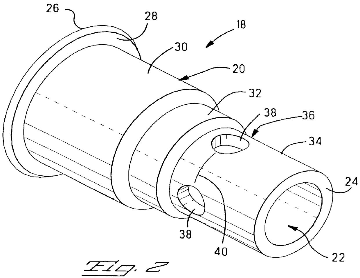
With reference first to FIG. 1, an electrical assembly particularly suited for incorporation of the present invention is shown generally at 2. The connector assembly 2 is mounted upon a substrate 4, such as a printed circuit board, that would typically have circuit traces disposed thereupon. The connector assembly 2 incorporates a basic housing 6 through which a plurality of contact receiving passageways 8 extend from a mating end 10 to a rear side 12. Electrical contacts are disposed within the passageways 8 and are adapted for mating with a complementary connector (not shown) on the mating end 10 and on the rear side 12 are configured to engage the conductive pathways on the printed circuit board 4. As this is a right angle connector, the housing 6 is further configured with L-shaped mounting features 13, such that a base 16 is established that sits upon the substrate 4. In order to anchor the connector assembly 2 to the substrate 4, board-lock components 18 would be used on eithe...


PUM


Abstract

PCT No. PCT/IB97/01251 Sec. 371 Date Apr. 12, 1999 Sec. 102(e) Date Apr. 12, 1999 PCT Filed Oct. 8, 1997 PCT Pub. No. WO98/16977 PCT Pub. Date Apr. 23, 1998An electrical connector assembly mountable to a substrate having an opening therein and configured to mate with a complementary connector, the connector assembly comprising a connector housing having contacts therein for mating with conductors associated with the substrate and the complementary connector, and a board-lock extending outward from the housing and receivable in the opening along a positioning portion; the connector assembly characterized in that the board-lock includes a weakened band along the positioning portion where the weakened band is located within the opening corresponding to the wall thereof, the weakened band including an engagement surface therealong, where the weakened band is constructed such that upon compression the board-lock deforms at the weakened band bringing the engagement surface against the wall of the opening.

Description

1. Field of the InventionThis invention relates to electrical connector assemblies and in particular to a locking feature for affixing the connector assembly, either electrically or mechanically, to a substrate, such as a printed circuit board.2. Summary of the Prior ArtIt is common to incorporate into electrical connector assemblies a board-lock or eyelet in order to anchor the connector assembly to a substrate, such as a printed circuit board. These board-locks may take on a number of different configurations and may be made of various materials, such as a molded plastic extension of the connector housing or a metallic member either an insert or a portion of a shielding housing. In some cases it is desirable to have the option of utilizing the board-lock as a conductor and most typically as a conductor of the ground-path between the shielding associated with the connector assembly and a ground plane established on the substrate. In this case, it is known to form a board-lock inser...

Claims


Application Information

Patent Timeline
IPC IPC(8): H01R12/20H01R12/00H01R13/73H01R12/55H01R12/58H01R12/71
CPCH01R12/7011H01R12/7064H01R12/7035H01R4/06
Inventor SOUISA, CORNELIUS FREDERIK
Owner THE WHITAKER CORP
Why Eureka
Try Eureka