Photosensor using side surface light

a technology of side surface light and photosensor, which is applied in the field of photosensors, can solve the problems of affecting the reception signal of stable light, the ratio of side beam to front beam is largely corrupted with time, and the front beam is further corrupted, so as to achieve stable light reception signal

Inactive Publication Date: 2000-08-22
CANON KK
View PDF7 Cites 20 Cited by
  • Summary
  • Abstract
  • Description
  • Claims
  • Application Information

AI Technical Summary

Benefits of technology

The present invention has been made in consideration of the above situation and has as its object to provide a photosensor in which side beams from a light emitting device are once irradiated on a light diffusing member and a light beam emitted from the surface of this light diffusing member as a light source is received by a light receiving device for monitoring, and which thereby realizes a stable reception of the monitoring light beam unaffected by changes in the emission output and the directivity characteristic of the light emitting device.
Accordingly, the side beams from the light emitting device are once irradiated on the light diffusing plate, and this changes point light sources from the light emitting device into a surface light source from the light diffusing plate. Consequently, the light receiving surface of the light receiving device can receive uniform light and so the light receiving device can output a stable light reception signal.

Problems solved by technology

Unfortunately, when the side beams from the light emitting device 1 are monitored by the light receiving device 2 as described above, the light emitting device 1 has two point light sources, i.e., a chip and the top of a resin mold encapsulating the chip when viewed from the light receiving device 2.
Consequently, the ratio of the side beam to the front beam is largely corrupted with time.
Also, the larger the power supply amount, the larger the side beam, the front beam, and the ratio of the side beam to the front beam is further corrupted.

Method used


Image

  • Photosensor using side surface light
  • Photosensor using side surface light
  • Photosensor using side surface light

Examples


first embodiment

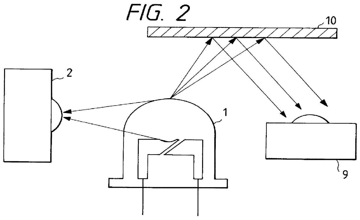
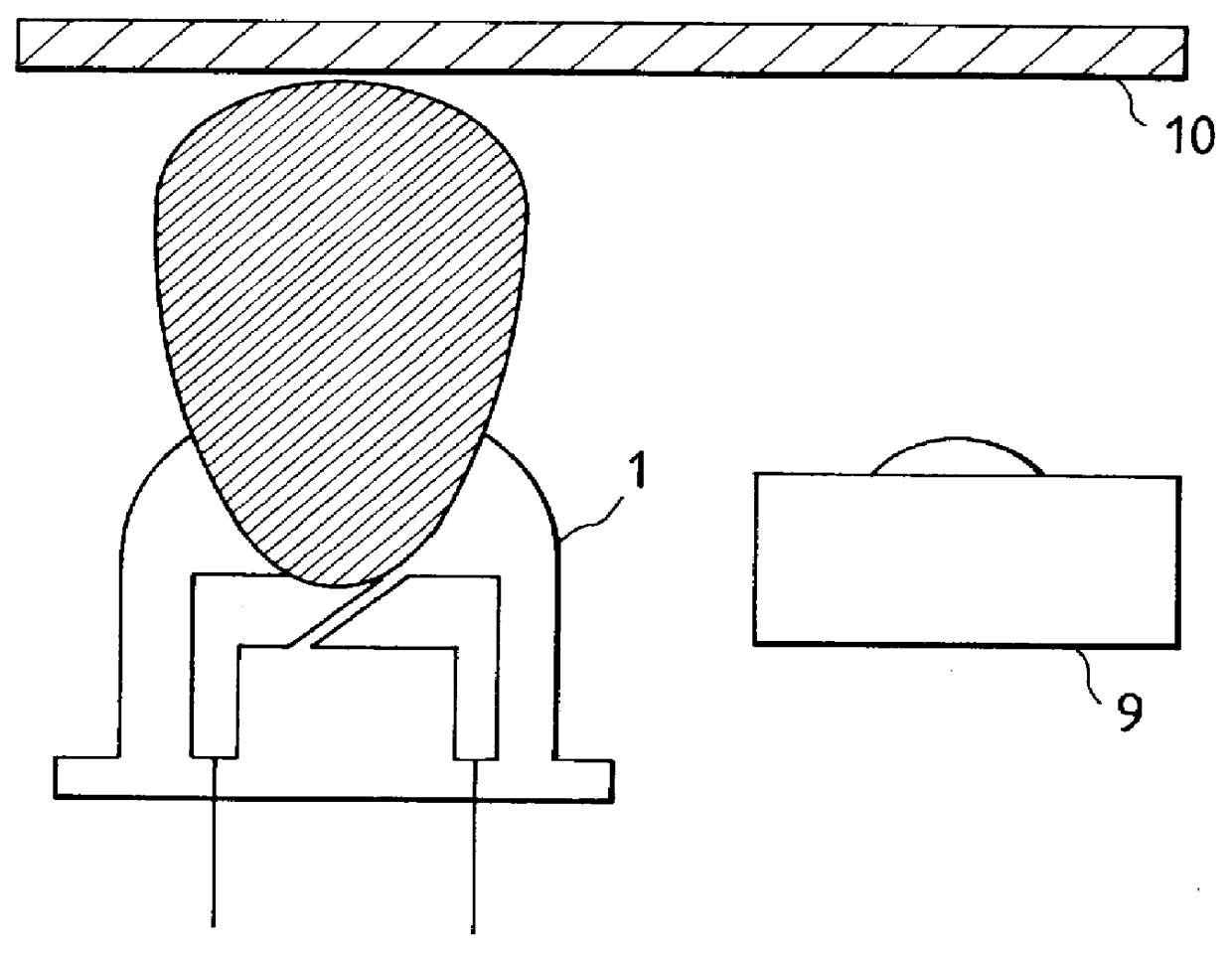
FIG. 7 is a view showing a photosensor of the present invention. In FIG. 7, this photosensor includes a light emitting diode (LED) 1 as a light emitting device, a light receiving device 2, and a diffusing plate 3. When viewed sideways, the light emitting device 1 has two point light sources, i.e., a chip (light emitting chip) of the light emitting device and the top of a resin mold. Side beams emitted from these light sources are once irradiated on the light diffusing member (to be referred to as a diffusing plate hereinafter) 3 inserted between the light emitting device 1 and the light receiving device 2. The side beams are diffused inside the diffusing plate 3 and irradiated as a surface light source from the diffusing plate 3 onto the light receiving device 2. The photosensor further includes a light receiving device 9 for receiving front beams from the light emitting device 1 and a medium 10 on which the front beams are irradiated.

In the photosensor with the above arrangement, t...

second embodiment

FIG. 9 is a view showing the photosensor of the present invention. The same reference numerals as in FIG. 7 denote the same parts in FIG. 9 and a detailed description thereof will be omitted. This photosensor shown in FIG. 9 uses a cap-like light diffusing plate (to be referred to as a light diffusing cap hereinafter) 5 instead of the diffusing plates 3 and 4 described above. FIG. 10 is a view in which a light emitting device 1 in FIG. 9 is viewed from the above (in the direction of an arrow A). Referring to FIG. 10, the light emitting device 1 consists of a resin mold 6 and a light emitting chip 7. The entire circumferential surface of the light emitting device 1 is covered with the light diffusing member.

Side beams irradiated from the light emitting device 1 enter the light diffusing cap 5 and entirely form diffused light. This diffused light is received by a light receiving device 2 as a surface light source from the light diffusing cap 5.

In the photosensor with the above arrange...


PUM


Abstract

A photosensor includes a light emitting device, a light receiving device for receiving a side beam from said light emitting device, and a light diffusing member disposed between a side surface of said light emitting device and said light receiving device.

Description

BACKGROUND OF THE INVENTION1. Field of the InventionThe present invention relates to a photosensor consisting of a light emitting device and a light receiving device and, more particularly, to a photosensor used in a density sensor unit of an image recording apparatus.2. Related Background ArtAn arrangement in which light from the front surface of a light emitting device 1 is irradiated on a certain medium 10 and the reflected light from the medium is detected by a light receiving device 9 is conventionally known as a photosensor. In this arrangement, the directivity characteristic of the light from the front surface of the light emitting device is generally as shown in FIG. 1. Also, a model in which side beams from a light emitting device 1 are received and monitored by a light receiving device 2 is as shown in FIG. 2. In a conventional photosensor, the light emitting device 1 and the light receiving device 2 are often arranged in positions as shown in FIG. 2 by taking account of t...

Claims


Application Information

Patent Timeline
Patent Type & Authority Patents(United States)
IPC IPC(8): G06K15/12H01L31/12
CPCG06K15/1214
Inventor SHIBA, HIROSHIMANO, HIROSHINAGAOKA, TOMOO
Owner CANON KK
Why Eureka
Try Eureka