Three-dimensional shape measuring apparatus

a three-dimensional shape and measuring apparatus technology, applied in the direction of measuring devices, instruments, using optical means, etc., can solve the problems of reducing the rate at which light passes through the pinhole (coefficient of utilization) and the measurement takes a long tim

Inactive Publication Date: 2000-08-22
TAKAOKA ELECTRIC MFG
View PDF4 Cites 57 Cited by
  • Summary
  • Abstract
  • Description
  • Claims
  • Application Information

AI Technical Summary

Benefits of technology

will hereinafter become more readily a

Problems solved by technology

This method, however, requires moving the object stage in the Z direction for each of a large number of points to be measured, and therefore takes a long time for measurement.
This slight shifting in the Z position causes errors.
In addition, deviations in scanning and sampling timing cause errors in the XY positions of the measured points of a confocal image.
However, there are following problems with the above conventional three-dimensional shape measuring apparatuses with an arrayed confocal imaging system.
In such a configuration, however, the rate at which the light passes through the pinholes (coefficient of utilization) decreases considerably, and it is difficult to obtain light with the intensity necessary for measurement.
Therefore, the diameter of the spot is relatively larger than that of the pinholes and it is difficult to sufficiently increase the coefficient of utilization of illuminating light.
However, a large-scale facility is needed for manufacturing this apparatus because of its very complicated structure.
Moreover, laser light must be used for the reflex hologram to fulfill its function, but laser light is prone to interfere and is not suited for measurement of a three-dimensional shape.
Therefore, measuring the height of such a point is impossible.
Furthermore, this apparatus cannot separate illuminating light and ref

Method used


Image

  • Three-dimensional shape measuring apparatus
  • Three-dimensional shape measuring apparatus
  • Three-dimensional shape measuring apparatus

Examples


Embodiment Construction

First, the three-dimensional shape measuring apparatus using an arrayed confocal imaging system of the first invention of this application is explained by way of embodiments.

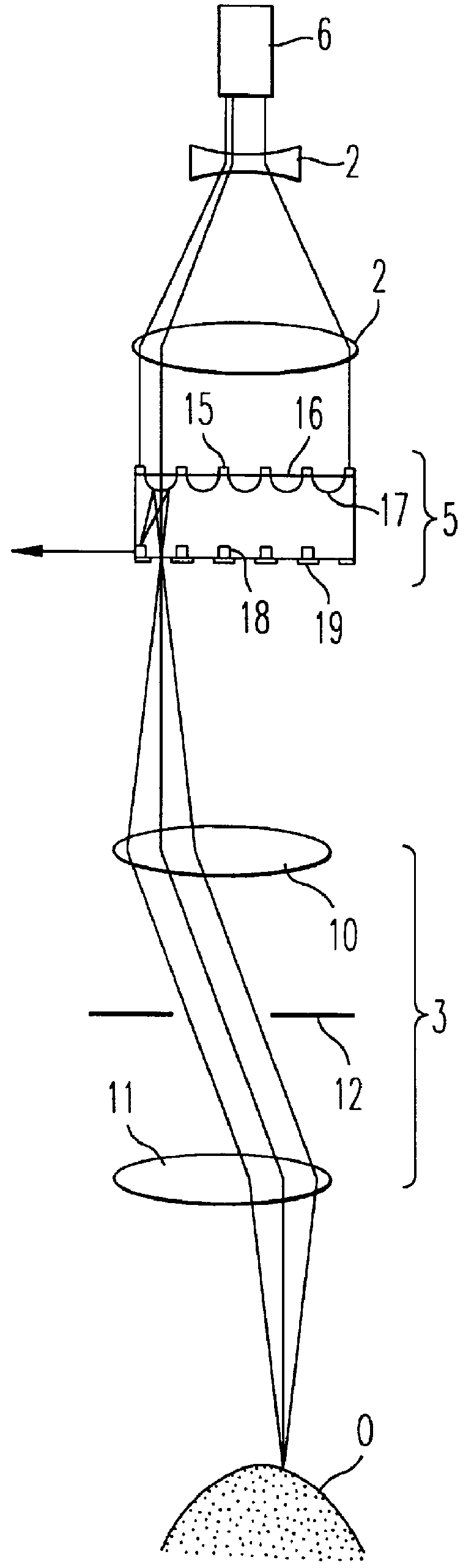
FIG. 5 shows an embodiment of the three-dimensional shape measuring apparatus using an arrayed confocal imaging system of the first invention of this application. The light emitted from a light source 6 passes through a pinhole 1 to become light from a point light source. The light from the pinhole 1 is refracted into parallel light rays by a collimator lens 7, and then polarized into linearly polarized light by a polarizer 20. The linearly polarized light next enters a light path diverging optical element 21. The light path diverging optical element 21 is a polarized-light beam splitter which allows linearly polarized illuminating light to pass through. The illuminating light which passes through the light path diverging optical element 21 enters the microlenses in a microlens array 17, and is converged at the ...


PUM


Abstract

A three-dimensional shape measuring apparatus using a confocal imaging system which has a new means for changing the distance in the Z direction between the object and the object-position-in-focus, instead of an object stage moved in the Z direction. This means shifts the object-position-in-focus in the Z direction by refraction. One means inserts a plurality of transparent flat plates between the objective lens and the object-position-in-focus in turn. Another means uses a transparent flat plate made of a material for which the refractive index changes according to the voltage applied and is disposed between the object and the object-position-in-focus.

Description

1. Field of the InventionThe present invention relates to a three-dimensional shape measuring apparatus, and particularly to a three-dimensional shape measuring apparatus using a confocal imaging system.2. Discussion of the BackgroundA three-dimensional shape measuring apparatus using a confocal imaging system is used for automatic inspections of minute products on production lines.The basic configuration of the confocal imaging system is shown in FIG. 1. Light emitted from a pinhole 1 passes through a half mirror 2. The light from the half mirror 2 is then converged by an objective lens 3 toward an object. The light which strikes the surface of the object is reflected. Of the reflected light, the light which enters the objective lens 3 is caused to converge by the objective lens 3, and is then deflected by the half mirror 2 toward the pinhole 4 which is disposed at the same position optically as the pinhole 1. The quantity (intensity) of the light passing through the pinhole 4 is m...

Claims


Application Information

Patent Timeline
IPC IPC(8): G01B11/24G01B11/02
CPCG01B11/026G01B11/24
Inventor ISHIHARA, MITSUHIRO
Owner TAKAOKA ELECTRIC MFG
Why Eureka
Try Eureka