Microchips and remote control devices comprising same

a technology applied in the field of microchips and remote control devices comprising same, can solve the problems of not being widely used in commercial remote control devices, unauthorized access being given to unauthorized persons, and transmitters and receivers being out of step by more than n+m steps, so as to achieve the effect of increasing security

Inactive Publication Date: 2000-08-22
MICROCHIP TECH INC
View PDF55 Cites 18 Cited by
  • Summary
  • Abstract
  • Description
  • Claims
  • Application Information

AI Technical Summary

Benefits of technology

It is a further object of the invention to provide a security system in which synchronization of the transmitter and receiver remote control devices can be achieved by a simple yet reliable and secure manner.
The unit number may be at least a one bit value. Although it may extend into thousands of bits and even more, it will be appreciated that the longer the unit number, the greater the security it offers but more expensive the microchip becomes.
The counter value is also preferably of more than a one bit length and may also extend into thousands of bits and even more, which will as would be appreciated, increase the security. The longer the counter value, however, the higher the cost.
The transmission value is preferably at least 16 bits long. It will be appreciated that if it is of a length less than 16 bits, it will be less secure and consequently it will be easier to decode.
Also according to the invention, the decoder means may comprise means for recognizing a panic command generated in the encoder means, and means for responding thereto. In addition, the decoder means may comprise means for recognizing other commands and / or more than one unit number with independent counters, without having to perform the decoding process more than once.

Problems solved by technology

However, because of their high cost and certain practical disadvantages, they are not widely used in commercial remote control devices.
Either of these shortcomings can lead to access being given to unauthorized persons.
Thus, in the event of non-agreement, and this will occur very often if the system is widely used in RF-devices, because of accidental reception from other users, this apparatus changes to an increased security mode, which is user unfriendly.
However, a serious problem in the operation of the system results when the situation occurs that the transmitter and receiver are out of step by more than n+m steps.
Both of the above situations are user unfriendly.
If this process is repeated often, it also presents a security risk.
In addition, the above-described systems are also vulnerable to a newly developed sophisticated "code grabber."

Method used


Image

  • Microchips and remote control devices comprising same
  • Microchips and remote control devices comprising same
  • Microchips and remote control devices comprising same

Examples


Embodiment Construction

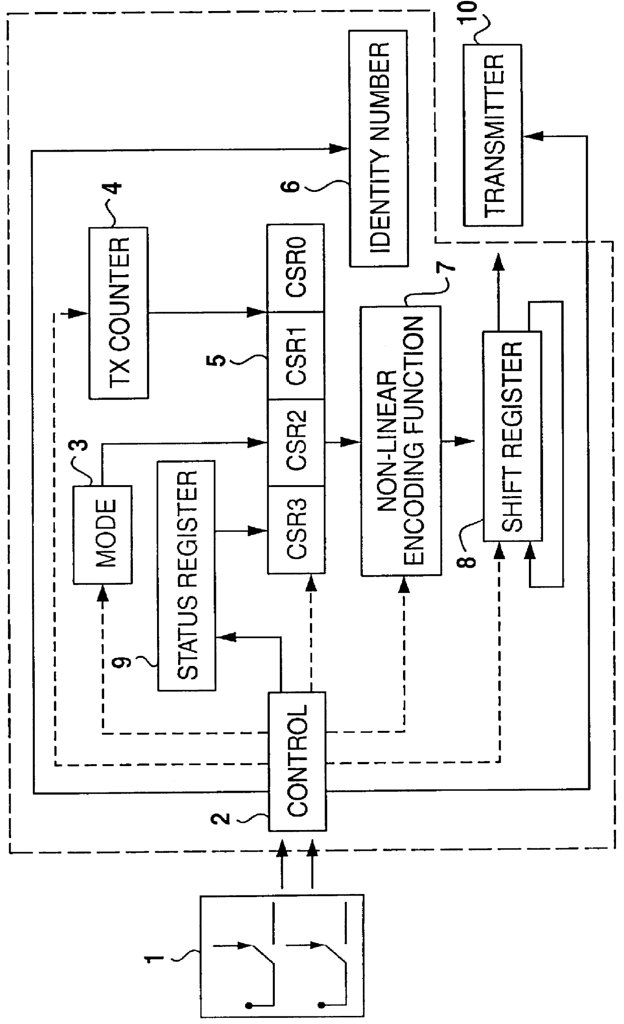
Referring to FIG. 1, the encoder microchip receives an input from a pair of switches (1), and comprises a control unit (2), a mode unit (3), a transmit counter (4), an input register (5) for holding an input word, an ID register (6) for holding an identity number, logic means (7) for performing a non-linear function, a shift register (8) for holding an encoded value and repeatedly feeding the encoded value to a transmitter (10), and a status register (9) for holding the configuration of the encoder microchip. The status register (9), the identity number (6) and the transmitter counter (4) are all registers or memory elements that can be programmed into the microchip and may be non-volatile (EEPROM) or volatile (RAM) memory with battery backup. As will be appreciated by those skilled in the art, the functions of the encoder microchip can be implemented in dedicated logic although a microprocessor based implementation is also possible.

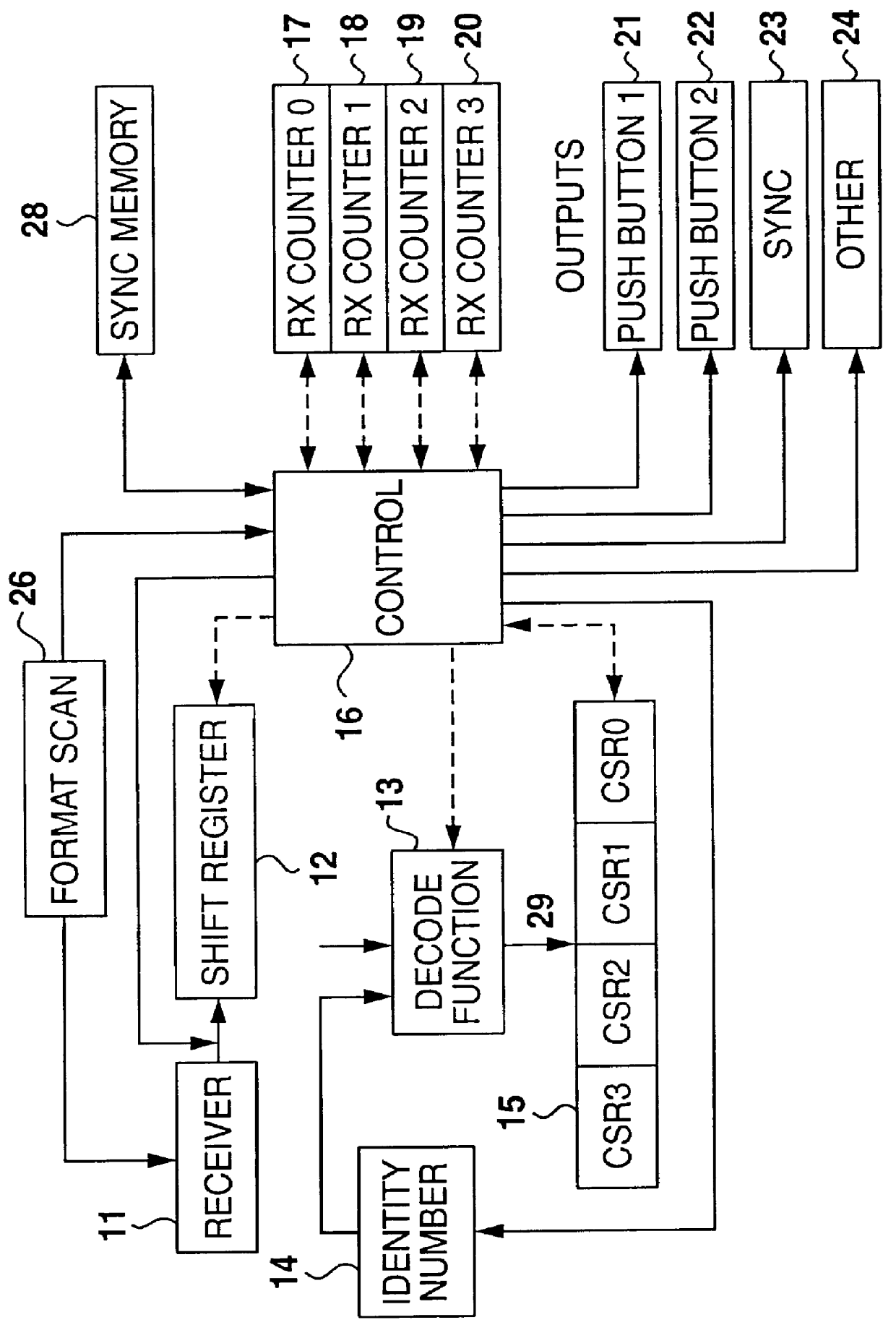
Referring to FIG. 2, there is shown a receiver (11...


PUM


Abstract

Encoder and decoder microchips suitable for use in remote control devices. The encoder microchip performs an encoding function on an identification number embedded in the said microchip and a combination of a unit number and a stepping counter value, so as to generate a transmission value which is only decodable by a related decoding function having access to the same identification number. The decoder microchip decodes the transmission value into a decoded unit number and a decoded counter value and means for comparing the decoded counter value with a decoder counter value range. The encoder and decoder microchips are provided with means for changing, e.g. in a preferred mode incrementing, the counter values by a number greater than one after a period of time, subsequent to the encoder microchip being activated or the decoder microchip receiving a transmission value. The encoder and decoder microchips are also provided with means for synchronizing the decoder microchip with a particular encoder microchip which has generated a synchronization command.

Description

This invention relates to security systems. More particularly, the invention relates to microchips suitable for use in remote control devices, to remote control devices comprising the said microchips and to a security system.Remote control via radio frequency or infra red media is well known and very popular for the control of car alarms, building alarms and automatic garage door equipment. Conventional remote control systems which are based on a uni-directional transmission with limited security features, are in common use and are available at relatively low prices. More sophisticated devices based on bi-directional transmission systems and extensive handshaking, are also available on the market and are known to the applicant. However, because of their high cost and certain practical disadvantages, they are not widely used in commercial remote control devices. The aforementioned conventional devices based on uni-directional transmission systems have two important shortcomings in th...

Claims


Application Information

Patent Timeline
Patent Type & Authority Patents(United States)
IPC IPC(8): G07C9/00E05B49/00H04L9/32H04Q9/00H04Q9/14
CPCG07C9/00182G07C2009/00222G07C2009/0023G07C2009/00246G07C2009/00769G07C2209/08E05B49/00
Inventor BRUWER, FREDERICK
Owner MICROCHIP TECH INC
Why Eureka
Try Eureka