Error-correcting decoder continuously adding flag signals to locations preceding a first location at which a difference between path metrics is lower than the threshold

a decoder and flag signal technology, applied in the field of error-correcting decoder equipment, can solve the problems of deteriorating efficiency of correction using "erasure" and achieve the effect of improving the error correction capacity of the error-correcting decoder and reducing the rate of erasure symbols for correct parts

Inactive Publication Date: 2000-08-22
MITSUBISHI ELECTRIC CORP
View PDF13 Cites 67 Cited by
  • Summary
  • Abstract
  • Description
  • Claims
  • Application Information

AI Technical Summary

Benefits of technology

An object of the present invention is to solve the above problem with the following: In a second decoding procedure of the present invention, a flag signal is added only to a result highly believed

Problems solved by technology

Consequently the efficiency of correcti

Method used


Image

  • Error-correcting decoder continuously adding flag signals to locations preceding a first location at which a difference between path metrics is lower than the threshold
  • Error-correcting decoder continuously adding flag signals to locations preceding a first location at which a difference between path metrics is lower than the threshold
  • Error-correcting decoder continuously adding flag signals to locations preceding a first location at which a difference between path metrics is lower than the threshold

Examples


embodiment 1

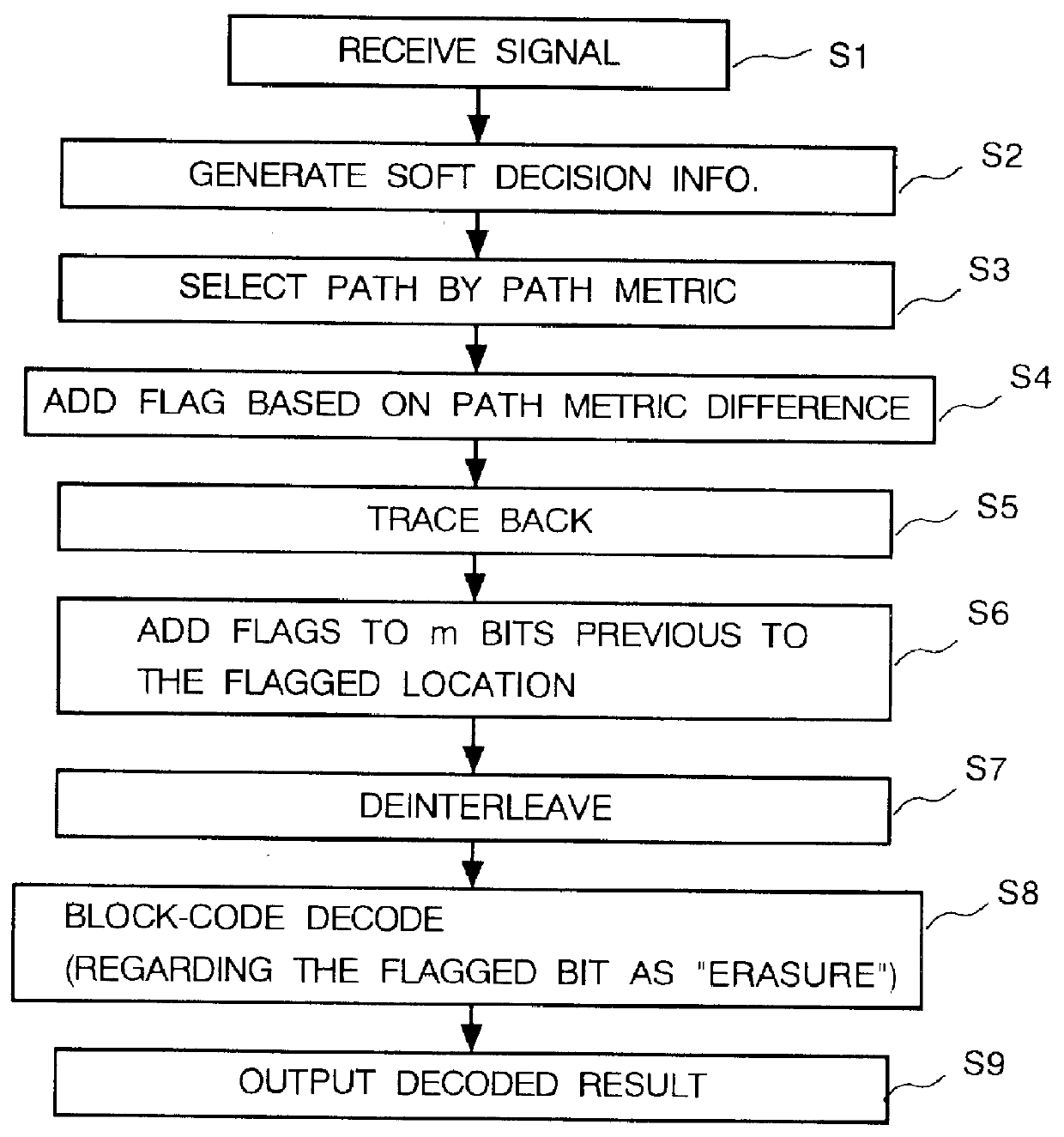
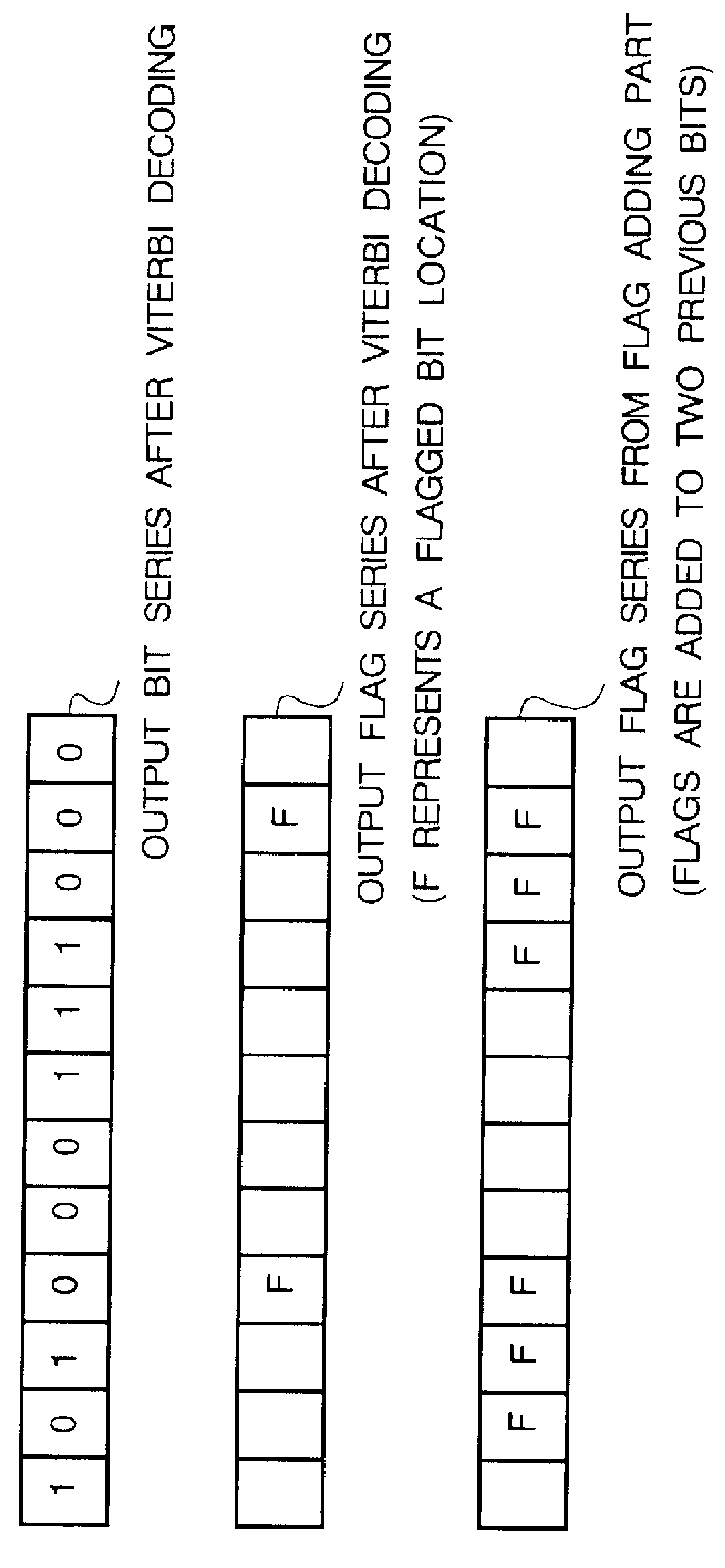
An error-correcting decoder for concatenated codes according to the first embodiment of the present invention will now be described. The main point of the present invention is described with reference to the analysis results showing deteriorated reliability in Viterbi decoding. With respect to data segments having low reliability in a trellis of Viterbi decoding, it is believed that the cause of the low reliability does not solely originate from the only path where the low reliability is estimated, but also from paths preceding the original path. Therefore, for the purpose of obtaining an improved decoding result, the present invention adds flag signals to all paths whose reliabilities are low and performs a second decoding with regard to the flagged locations as "erasure locations".

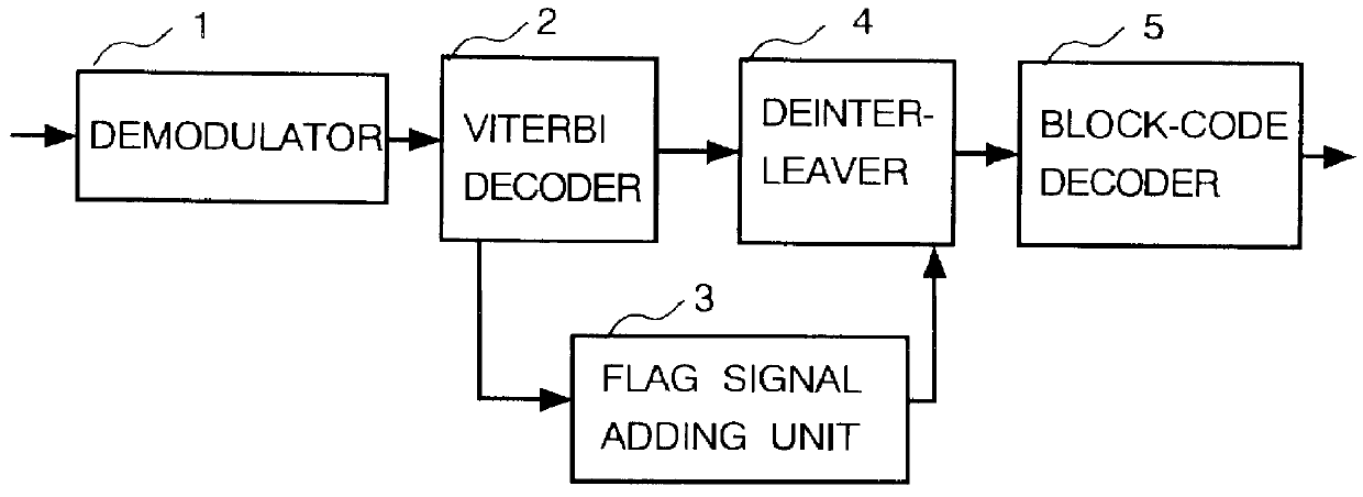
FIG. 1A illustrates an operation flow of error-correcting decoder according to the present embodiment and FIG. 1B shows a configuration of the error-correcting decoder. In FIG. 1B, a demodulator 1, a Vit...

embodiment 2

FIG. 3A illustrates an operation flow of an error-correcting decoder according to the second embodiment and FIG. 3B shows a configuration of the error-correcting decoder. In FIG. 3B, a symbol separator 6 for separating information into symbols composed of plural bits, and a Reed-Solomon (RS) decoder 7 are utilized in place of the block-code decoder 5 of FIG. 1B. The other elements in FIG. 3B, the demodulator 1, the Viterbi decoder 2, the flag signal adding unit 3, and the deinterleaver 4 are substantially equal to the elements correspondingly numbered in Embodiment 1 and shown in FIG. 1B. FIGS. 4A through 4E illustrate process examples performed by the error-correcting decoder of FIG. 3B in the case of receiving a digital signal serial stream of "one symbol for every three bits" shown in FIG. 4A which is similar to FIG. 2B.

The operation of the error-correcting decoder configured as depicted in FIGS. 3A and 3B will now be described. Operations up to the deinterleaver 4 are the same a...

embodiment 3

FIG. 5A illustrates an operation flow of an error-correcting decoder according to the third embodiment and FIG. 5B shows a configuration of the error-correcting decoder therefore. An object of the present configuration is to enhance reliability. In FIG. 5B, a CR (Cyclic Redundancy) checking unit (means) 8 and a flag signal adding unit (means) 9 are shown. The other elements are substantially similar to the ones correspondingly numbered in Embodiment 1.

Operations S1 through S5 in the error-correcting decoder of the present embodiment are the same as the previous embodiments. At S21 in FIG. 5A, CR checking is performed for hard decision information determined by Viterbi decoding. If an error bit is detected in CR check of S21, then at S22 in FIG. 5A, a flag signal is added to the error bit by the flag signal adding unit 9. Viterbi decoding, CR checking and flag signal adding are repeatedly performed for data received one by one. At S7 in FIG. 5A, the order of the hard decision informa...


PUM


Abstract

In an error-correcting decoder, in which an input digital signal including reliability information is decoded by using a Viterbi algorithm as a first decoding process and a final decoded result is obtained by block-code decoding as a second decoding process, a flag signal is added to a location where a value of reliability of path metric determined by the Viterbi algorithm is lower than a threshold, as an original flagged location. A flag signal adding unit continuously adds flag signals to locations, from the original flagged location to locations preceding the originally flagged location, after back tracing. The flagged locations are then regarded as erasure locations in the block-code decoding process.

Description

1. Field of the InventionThe present invention relates to an error-correcting decoder apparatus and method for correcting errors generated in digital radio communications and others.2. Description of the Related ArtFIG. 20 of the accompanying drawings is a block diagram showing a conventional error-correcting decoder for concatenated codes disclosed in Unexamined Japanese Patent Publication No. 5-235784. In FIG. 20, an RS (Reed Solomon) encoder 101, an interleaver 102, a convolutional encoder 103, a transmission path 104, a convolutional decoder 105, a first deinterleaver 106, a comparator 107, a second deinterleaver 108, and an RS decoder 109 are shown. The RS encoder 101 adds an RS-code check symbol to the data. The interleaver 102 interleaves the transmission order of RS-encoded data. The convolutional encoder 103 convolutionally encodes data output from the interleaver 102 and the transmission path 104 transmits the data. The convolutional decoder 105 convolutionally decodes its...

Claims


Application Information

Patent Timeline
IPC IPC(8): H04L1/00H03M13/41H03M13/00G06F11/10H03M13/29
CPCH03M13/00H03M13/4161H04L1/0054H04L1/0065H04L1/0066
Inventor NAKAMURA, TAKAHIKOYOSHIDA, HIDEOFUJITA, HACHIRO
Owner MITSUBISHI ELECTRIC CORP
Why Eureka
Try Eureka