Submersible appartus for generating electricity and associated method

a submerged apparatus and submerged technology, applied in the direction of machines/engines, stators, liquid fuel engines, etc., can solve the problem that the hydroelectric generating units must be massiv

Inactive Publication Date: 2000-08-29
MILLIKEN LARRY D
View PDF21 Cites 265 Cited by
  • Summary
  • Abstract
  • Description
  • Claims
  • Application Information

AI Technical Summary

Benefits of technology

The present invention has met the hereinabove described needs. The invention provides an apparatus and an associated method of generating electricity from generally unidirectional liquid flow by means of counter-rotatable liquid-driven motors contained in a buoyant structure fully immersed in said fluid. The liquid-driven motors generally comprise at least one array of radially-oriented vertical vanes. Each such vane preferably comprises two or more overlapping pivotable vertical subvanes that pivot during rotation of the motor such that each subvane overlaps the adjacent

Problems solved by technology

In order to be of sufficient size and capacity to be effec

Method used


Image

  • Submersible appartus for generating electricity and associated method
  • Submersible appartus for generating electricity and associated method
  • Submersible appartus for generating electricity and associated method

Examples


example

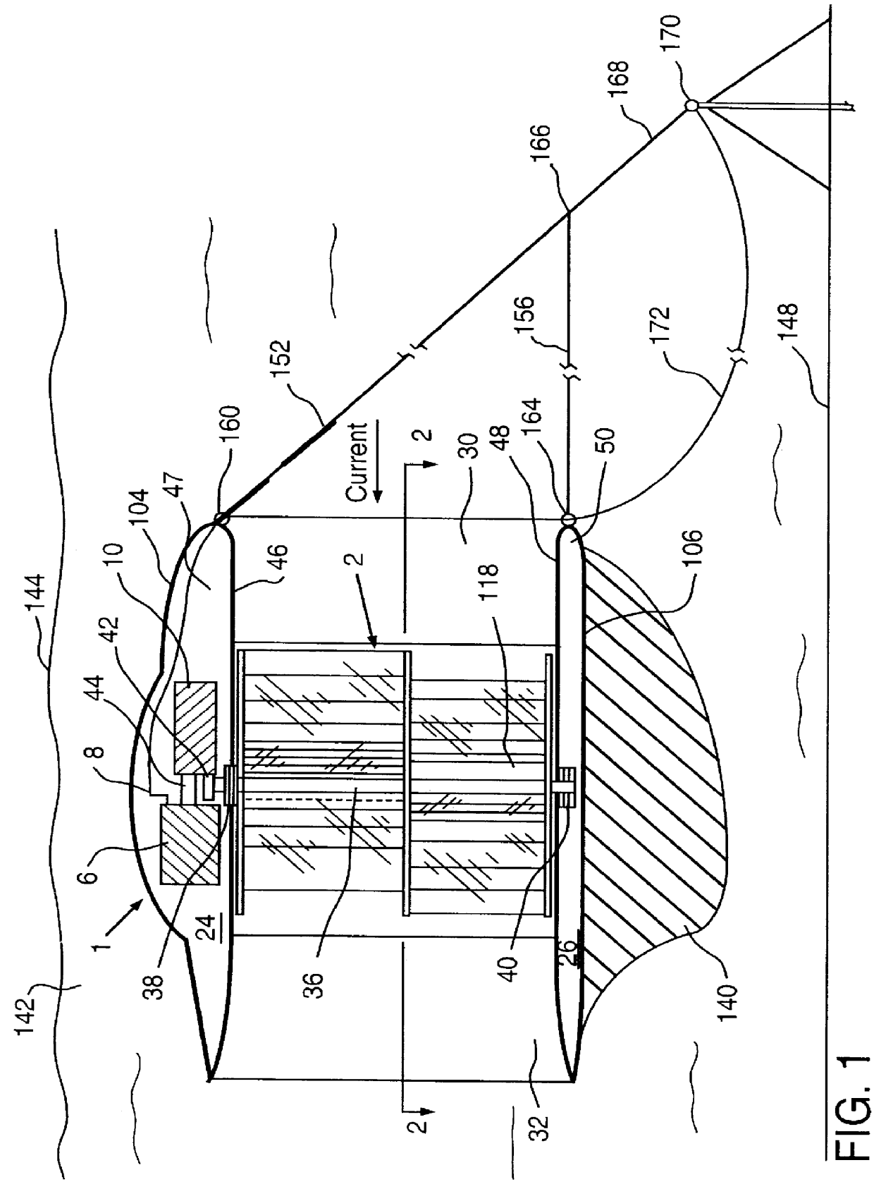
Referring to FIG. 1, a specific preferred example will be considered. A geared drive unit 10 is a gear box housing gears that increase the slow rotational speed of approximately 3 to 4 rotations per minute of the hydrodynamic motors, by about 300 times such that each electric generator 6 rotates at a speed of 900 to 1,200 rotations per minute. Hollow top portion 24 of the buoyant structure contains two bulges (one behind the other) in top wall 104 to accommodate two electric generators and two geared drive units situated such that each generator / drive unit combination is situated in enclosed top space 47 above one counter-rotating hydrodynamic motor. The bulges in top wall 104 contain access ports (not shown) that permit access to enclosed top space 47 in order to service and maintain said electric generators, said geared drive units, and upper bearings 38 contained therein when buoyant housing 1 is floated to the surface for periodic maintenance. Access to lower bearing 40 in enclo...


PUM


Abstract

A fully submersible apparatus for generating electricity from liquid flow as in an ocean or river current. A buoyant structure is fully submersible and has at least one pair of counter-rotating side-by-side motors with a plurality of angularly spaced radial vanes each having a plurality of rotatable subvanes such that current impinging upon the motor will impinge on a closed or solid vane to effect rotation of the motor and its shaft during a first phase of the rotational cycle and will impinge on open vanes for free passage therethrough on the return or second phase of rotation of the motor. Motors may also be provided with vanes in overlying and underlying relationship. An associated method is provided.

Description

1. Field of InventionThis invention relates to improved submersible apparatus for generating electricity from unidirectional liquid flow and a related method. More specifically, the invention relates to an efficient, environmentally safe method of generating electrical power from the energy contained in ocean currents and river currents and the like.2. Description of Related ArtAs demand for electricity has grown with an ever increasing world population, the need for non-polluting, renewable alternative energy sources to replace fossil fuels has grown dramatically. Some of the alternative sources that have been considered and / or developed commercially during the last half of the twentieth century include those associated with wind, wave, tide, ocean current, river current, ocean thermal differential, nuclear, and geothermal energy.The well known commercial limitations of nuclear power, geothermal power, and generation based upon differential thermal energy have eliminated these proc...

Claims


Application Information

Patent Timeline
IPC IPC(8): F03B17/00F03B17/06
CPCF03B17/065F05B2260/72F05B2260/78Y02E10/28Y10S415/907Y10S415/906Y02E10/30Y02E10/20
Inventor MILLIKEN, LARRY D.
Owner MILLIKEN LARRY D
Why Eureka
Try Eureka