Current collector for a fuel cell and method of making the same

a technology of current collector and fuel cell, which is applied in the direction of cell components, final product manufacturing, sustainable manufacturing/processing, etc., can solve the problems of loss of electrolyte, oxide layer formation on the surface of these components, and the current collector provided for the cathode is subject to severe corrosion effects

Inactive Publication Date: 2000-09-12
DAIMLER AG
View PDF12 Cites 26 Cited by
  • Summary
  • Abstract
  • Description
  • Claims
  • Application Information

AI Technical Summary

Problems solved by technology

Secondly, the current collectors form the passages or spaces necessary for supplying the reaction gases to the cathode or the anode respectively.
Due to the supply of air or other oxygen-containing gas, and the high operating temperature, the current collector provided for the cathode is subject to severe corrosion effects.
Nonetheless, it has been found in practice that oxide layers form on the surfaces of these components during operation of the fuel cell.
While these oxide layers are mostly electrically well conducting, they lead to a loss of the electrolyte however.
In this manner, the electrolyte is chemically broken down and lost, which leads to a degradation of the cell and therewith a decrease in the cell output power.
Thus, the exposed surface of the current collector can lead to the correspondingly greatest loss of electrolyte if corrosion takes place.
%, because otherwise an excessively high electrical resistance will arise at the contact area.

Method used


Image

  • Current collector for a fuel cell and method of making the same
  • Current collector for a fuel cell and method of making the same
  • Current collector for a fuel cell and method of making the same

Examples


Embodiment Construction

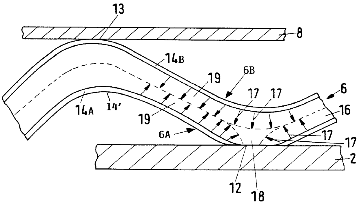
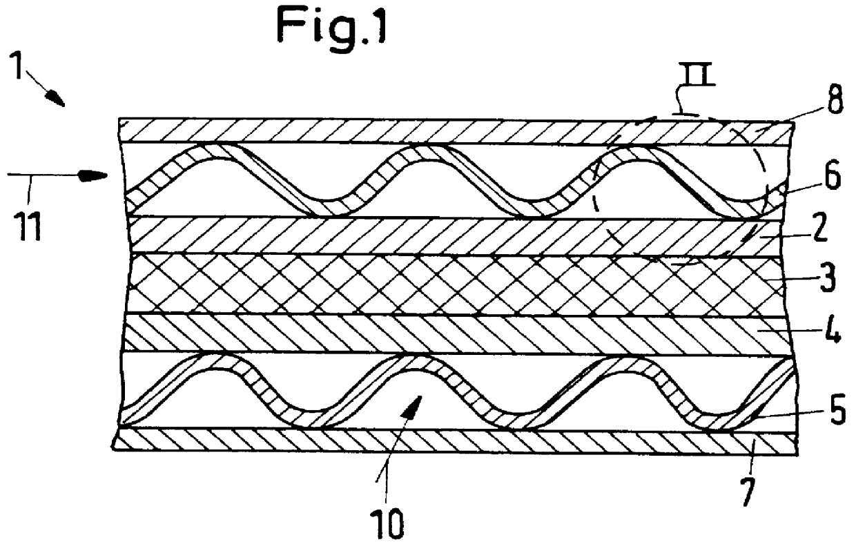
A molten carbonate fuel cell comprises a plurality of individual fuel cell units 1 stacked on top of one another. FIG. 1 shows an individual fuel cell unit 1 comprising a cathode 2, a porous matrix 3 saturated with a molten electrolyte, an anode 4, an anode current collector 5, a cathode current collector 6, a bottom separator plate 7, and a top separator plate 8. The components are arranged with the porous matrix 3 sandwiched between the cathode 2 and the anode 4, the cathode current collector 6 arranged between and contacting the top separator plate 8 and the cathode 2, and the anode current collector 5 arranged between and contacting the bottom separator plate 7 and the anode 4. The cathode 2 consists essentially of a porous metal oxide, for example. The anode 4 consists essentially of a porous sintered metal plate, for example.

Both the anode current collector 5 and the cathode current collector 6 are respectively gas permeable and corrugated with a wavy cross-sectional shape. Th...


PUM

PropertyMeasurementUnit
thicknessaaaaaaaaaa
thicknessaaaaaaaaaa
operating temperatureaaaaaaaaaa

Abstract

A molten carbonate fuel cell is constructed of plural stacked individual cell units, that each respectively include a porous, electrolyte saturated matrix (3) sandwiched between a cathode (2) and an anode (4), and current collectors (5, 6) respectively arranged between the anode (4) and a first separator plate (7), and between the cathode (2) and a second separator plate (8). Especially the cathode current collector (6) includes a stainless steel core (16) that is coated on at least one surface with an aluminum-containing layer (14). Preferably both surfaces of the stainless steel core (16) are coated with aluminum-containing layers (14A, 14B), except for a contact area (12) at which the stainless steel core (16) directly contacts the cathode (2). The aluminum-containing layer (14) prevents or minimizes the occurrence of an oxidation reaction that would otherwise lead to significant loss of the electrolyte.

Description

PRIORITY CLAIMThis application is based on and claims the priority under 35 U.S.C. .sctn.119 of German Patent Application 197 35 854.3, filed on Aug. 19, 1997. The entire disclosure of German Patent Application 197 35 854.3 is incorporated herein by reference.The invention relates to a current collector comprising a stainless steel sheet, and especially such a current collector arranged at the cathode of a molten carbonate fuel cell (MCFC), which for example comprises a plurality of stacked fuel cell units separated from one another by respective separator plates. The invention further relates to a method of making such a current collector.BACKGROUND INFORMATIONA molten carbonate fuel cell typically comprises a stack of individual cells or cell units. Each individual cell comprises a cathode and an anode, with their associated current collectors, and a matrix saturated with the molten electrolyte arranged between the two respective electrodes. A fusible fluid alkali carbonate mixtur...

Claims


Application Information

Patent Timeline
Patent Type & Authority Patents(United States)
IPC IPC(8): H01M8/02H01M8/14H01M8/0206H01M8/021H01M8/0228
CPCH01M8/0206H01M8/021H01M8/0228H01M2008/147H01M2300/0051Y02E60/50Y02E60/526Y02P70/50
Inventor NITSCHKE, FELIXWIND, JOERG
Owner DAIMLER AG
Why Eureka
Try Eureka