Check patentability & draft patents in minutes with Patsnap Eureka AI!

Method and device for separating groups of flat products from each other, and a folding machine comprising said device

a flat product and folding machine technology, applied in the field of flat product separating groups, can solve the problems of complex and expensive systems known at the moment, and achieve the effect of simple and reliabl

Inactive Publication Date: 2000-09-19
FABIO PERINI SPA
View PDF13 Cites 18 Cited by
  • Summary
  • Abstract
  • Description
  • Claims
  • Application Information

AI Technical Summary

Benefits of technology

The object of the present invention is to provide a separating device for the separation of packs of flat articles taken from a stack of continuously fed articles, which is simpler and more reliable than the conventional devices.
In the return path, the sliders may be accumulated and pushed by the same phase displacement means which takes individual pairs of sliders from the forward path and transfers them to the return path. Conversely, a return actuating means associated with said return portion of said closed path may be provided, to return the sliders to the start of the forward portion of the path. The actuating means may consist of a cylinder and piston pushing system, a pneumatic system or, preferably, a flexible member of the belt or equivalent type, which engages with the sliders to propel them in a direction opposite to the direction of advance of the articles in the device. For this purpose it is possible to provide bristles interacting with the separating fingers associated with one of said guides, while the separating fingers associated with the other guide may be coupled (as a result of special shaping) to the fingers engaged by the bristles of the flexible member or other actuating means. This solution is particularly simple and reliable, and eliminates any type of reciprocating movement as well as the consumption of compressed air.

Problems solved by technology

The systems known at the present time are complex and expensive.

Method used


Image

  • Method and device for separating groups of flat products from each other, and a folding machine comprising said device
  • Method and device for separating groups of flat products from each other, and a folding machine comprising said device
  • Method and device for separating groups of flat products from each other, and a folding machine comprising said device

Examples


Embodiment Construction

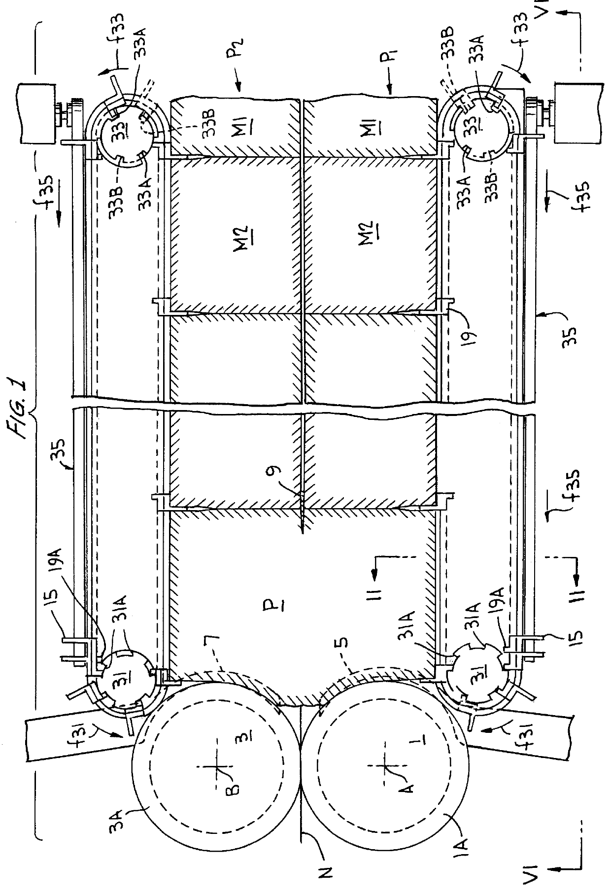
In the attached drawing, the numbers 1 and 3 indicate two folding rollers of a folding machine for the formation of a stack P of napkins. The folding rollers 1 and 3, which rotate about two vertical axes A and B, have annular grooves 1A, 3A which house curved arms 5 and 7 which detach the folded material from the roller and push it against the stack P of previously formed articles leaving the machine. A continuous strip material N, which may be folded along a longitudinal line, is fed into the throat formed between the two rollers, these rollers being associated systems of a known type which fold the material leaving the throat once around the roller 1 and once around the roller 3 to produce a stack of material folded in a zigzag configuration. With each fold, the corresponding curved arm 5, 7 detaches the material from the roller and pushes it towards the previously formed stack P.

The operation of the folding machine described in summary form is known and therefore will not be illu...


PUM

PropertyMeasurementUnit
Fractionaaaaaaaaaa
Thicknessaaaaaaaaaa
Flexibilityaaaaaaaaaa

Abstract

PCT No. PCT / IT97 / 00016 Sec. 371 Date Jul. 27, 1998 Sec. 102(e) Date Jul. 27, 1998 PCT Filed Jan. 24, 1997 PCT Pub. No. WO97 / 28076 PCT Pub. Date Aug. 7, 1997A device for separating from each other packs or groups of flat articles including a channel for the advance of the articles and, associated with the channel, a plurality of separating fingers which are movable along a closed path is described. On each side of the advance channel at least one pair of guides, placed one above the other and having substantially equal extensions, is provided to form the closed path. Pairs of sliders are disposed along the guides, and each slider carries at least one corresponding separating finger. A phase displacement means, which temporarily moves the first slider away from the second slider of each pair to move one pack of articles away from a following pack, is disposed at the end of the forward portion.

Description

The present invention relates to a device and to a corresponding method for separating packs or groups of flat products, each containing a predetermined number of articles and being continuously fed to be sent, for example, to a packaging machine.Devices of this type are frequently combined with machines for forming paper napkins and similar products. They normally have a channel for the advance of the articles and, associated with said channel, a plurality of separating fingers which are movable along a closed path comprising a forward portion, which is parallel to the channel for the advance of the articles and in which the separating fingers advance parallel to and simultaneously with the articles, and a return portion.Paper napkins are formed with forming machines comprising a pair of folding rollers with vertical axes forming a throat through which is fed a paper strip material which is normally folded along a longitudinal line. A system of clamps or suction holes associated wi...

Claims


Application Information

Patent Timeline
IPC IPC(8): B65H33/00B65H45/20B65H33/02B65H45/12B65H33/18
CPCB65H33/02B65H45/20B65H2301/4214B65H45/28B65H33/18
Inventor GHILARDI, MAURO
Owner FABIO PERINI SPA
Features
  • R&D
  • Intellectual Property
  • Life Sciences
  • Materials
  • Tech Scout
  • Unparalleled Data Quality
  • Higher Quality Content
  • 60% Fewer Hallucinations
Learn More