Reluctance motor

a technology of resistance motor and resistance, applied in the direction of synchronous motor, magnetic circuit rotating parts, magnetic circuit shape/form/construction, etc., can solve the problems of unfavorable decrease in generated torque, portion may not be able to move, and not the cas

Inactive Publication Date: 2000-09-19
OKUMA CORP
View PDF6 Cites 114 Cited by
  • Summary
  • Abstract
  • Description
  • Claims
  • Application Information

AI Technical Summary

Problems solved by technology

However, in reality, this is not the case.
When magnetic flux leaks are generated, the total magnetic flux may shift the N poles and S poles from the positions indicated in FIG. 16, causing the unfavorable decrease in generated torque.
When the rotor 2 rotates, this thin portion may not be able to withstand the centrifugal force generated on the rotor 2, and may thus deform or break.
This situation results in further decrease in generated torque.
Such an arrangement, however, presented more difficult conditions relating to centrifugal force because, further to the difficulty of withstanding centrifugal force only by the mechanical strength of the periphery portion 7, additional centrifugal force is generated by the permanent magnets 4A,.
Another problem to be addressed is that, as the internal shape of the rotor is rather complex, rotor mechanical strength is insufficient.
A further problem exists when many expensive permanent magnets are used, as in the example of FIG. 20.
Overall cost increases with the costs of permanent magnets and the costs for assembling those magnets.
Another problem is the unfavorable increase of torque ripples which result from disposing permanent magnets on the internal portions of the rotor or from taking measures to increase rotor mechanical strength.
A further problem is the insufficient rotor mechanical strength due to the many empty portions inside the rotor structure.

Method used


Image

  • Reluctance motor
  • Reluctance motor
  • Reluctance motor

Examples


Embodiment Construction

Embodiments of the present invention will now be described referring to the accompanying drawings. Descriptions will be omitted for components indicated by the same reference numerals as those that appeared in FIGS. 15 to 20 of the background art, as those components have identical functions and effects.

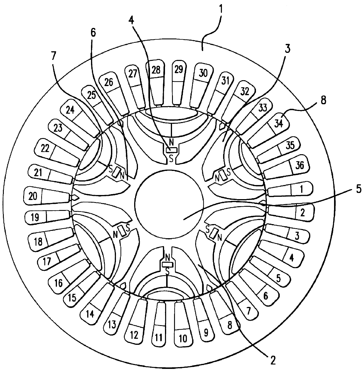
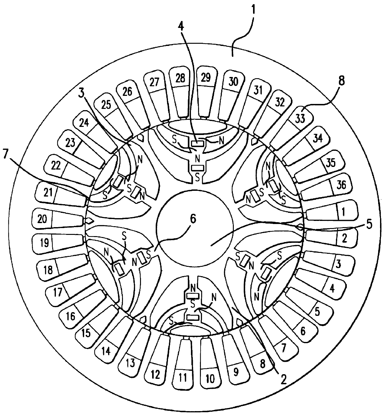
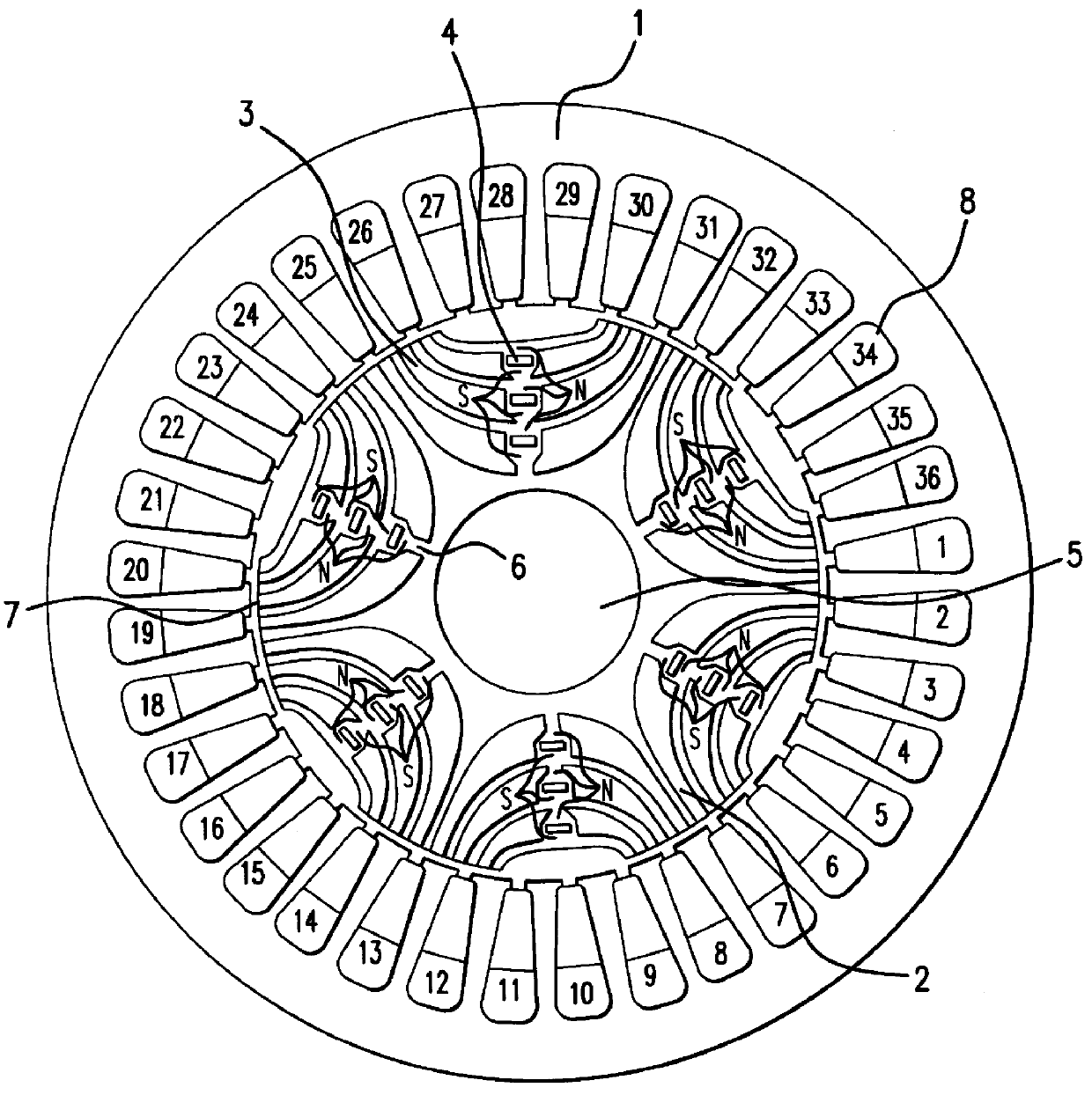
FIG. 1 is a diagram illustrating a cross-sectional structure of a rotor 2 and the surrounding stator 1 in a reluctance motor. In FIG. 1, among the connecting portions 6 present in the rotor 2, only the connecting portions 6 closest to the motor shaft 5 are provided with permanent magnets 4. The rotor 2 has a salient pole structure, and the slits 3 are made as wide as possible. These measures are taken to reduce leaking magnetic flux. Further, the connecting portions 6 having permanent magnets 4 are formed to have the least width necessary to withstand the centrifugal force. This is also one of the measures to minimize leaking magnetic flux. While permanent magnets are disposed on onl...


PUM


Abstract

A reluctance motor is provided that reduces leaking magnetic flux. To generate magnetic flux between adjacent magnetic poles in a rotor 2, permanent magnets 4 are disposed in approximate centers of split magnetic paths near a borderline area between two magnetic poles in an internal portion of the rotor. Further, each of slots 8 in a stator 1 is wound with a coil of a corresponding phase such that the vector phase and amplitude expressed by the products of the number of coil turns and the amount of passing current, namely, ampere-turns, become almost identical for each of the slots. By reducing leaking magnetic flux according to this arrangement, generated torque can be increased. As the rotor mechanical strength is enhanced, the rotor can be safely driven at a higher speed. A practical motor is obtained that simultaneously achieves improved motor characteristics and reduced torque ripples.

Description

1. Field of the InventionThe present invention relates to a reluctance motor, and particularly to a rotor structure thereof.2. Description of the Background ArtAmong motors presently used in many technical fields, there are motors that comprise a rotor formed of a material having high magnetic permeability rather than of a permanent magnet, and having a rotor cross-sectional structure such as shown in FIG. 15 wherein a plurality of nearly-insulated split magnetic paths are disposed between adjacent poles. Such motors are known as reluctance motors. As illustrated in FIG. 15, a rotor 2 of a typical reluctance motor is provided with a plurality of slits 3, in addition to a hole for receiving a motor shaft 5. These slits 3 serve as the basis for forming magnetic paths in the rotor 2. Specifically, as known in the conventional art, when electric current is made to flow in coils wound in slots 8 (FIG. 17) of a stator surrounding the rotor 2, magnetic flux is generated between the energiz...

Claims


Application Information

Patent Timeline
Patent Type & Authority Patents(United States)
IPC IPC(8): H02K1/27H02K19/22H02K19/02H02K19/10H02K19/16H02K1/22
CPCH02K1/246H02K19/103H02K19/22H02K2201/06
Inventor NASHIKI, MASAYUKIYOKOCHI, TAKANORI
Owner OKUMA CORP
Why Eureka
Try Eureka