

Radio receiver
a receiver and radio technology, applied in the field of radio receivers, can solve the problems of erroneous detection of fcch timing, deterioration of response characteristics of band pass filters, and inability to detect fcch at all,
- Summary
- Abstract
- Description
- Claims
- Application Information
AI Technical Summary
Problems solved by technology
Method used
Image

Examples
first embodiment
(1) First embodiment
(1-1) General Configuration of the Embodiment
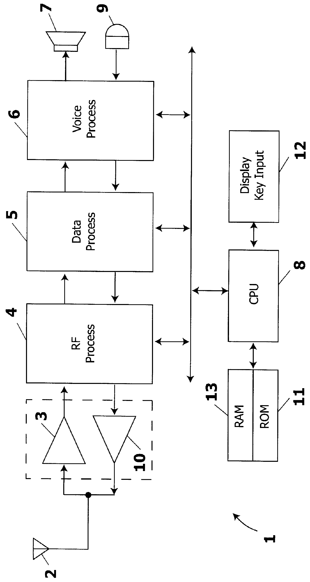
Referring to FIG. 2, 1 generally denotes a terminal of a digital cellular system, which receives a transmitted signal sent out from a base station with its antenna 2, and outputs the received signal thus obtained to an amplifier circuit 3 through an antenna coupler (not shown).
In this case, the amplifier circuit 3 amplifies the received signal with a predetermined gain, and then outputs it to an RF processing circuit (RF processor) 4. The RF processing circuit 4 frequency converts the received signal by using a predetermined local oscillation signal, the terminal 1 thereby being arranged so as to selectively receive a desired channel by switching the frequency of the local oscillation signal.
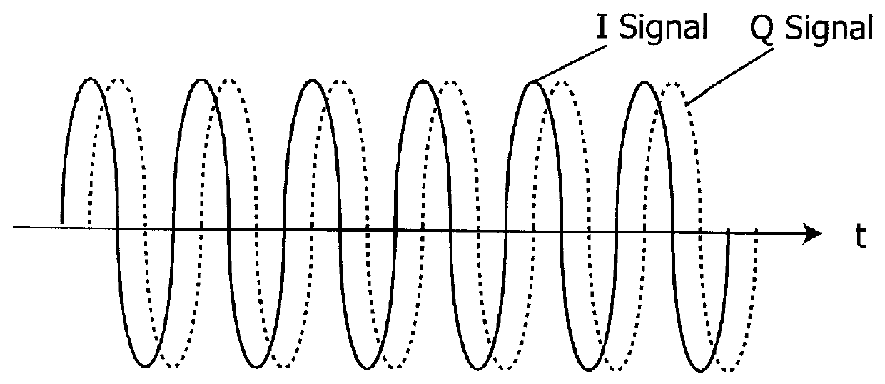
Moreover, the RF processing circuit 4 orthogonally detects the frequency converted received signal to demodulate an I signal which is in synchronization with the reference phase of the received signal, and to demodulate a Q signal....
second embodiment
(2) Second Embodiment
In this embodiment, the reference signal is generated by an accumulator 20 as shown in FIG. 6, and the correlation value is detected between this reference signal and the I and Q data.
That is, in this embodiment, the data processing circuit 5 outputs eight-bit data from the accumulator 20, adds this data with a predetermined constant in an adder circuit 21, and then stores the result of addition in the accumulator 20 again.
Thus, the data processing circuit 5 is designed to perform this addition in synchronization with the operation of the analog-to-digital convertor circuit 16, and to output the most significant bit (MSB) in the accumulator as a reference signal IT for the I data.
In addition, the data processing circuit 5 delays the I data reference signal by one sampling cycle in a predetermined delay circuit so as to generate and output a reference signal QT for the Q data from the I data reference signal.
Here, in this embodiment, the constant output to the ad...
third embodiment
(3) Third Embodiment
When, in the second embodiment, the frequency of the reference signal is switched by changing the constant to be cumulatively added as described above, there is a shortcoming in that much time is ultimately taken for detecting the FCCH.
Therefore, in this embodiment of FIG. 8, reference signals with different frequencies are generated by phase correlators 25A, 25B, and 25C by cumulatively adding constants with different values. Then, the correlators 25A, 25B, and 25C perform calculation of the equation (1) between the I and Q data consisting of the received signal and each reference signal.
A judgment circuit 26 performs calculation of the equations (2) and (3) on the results of calculation of the equation (1) output from the correlators 25A to 25C, respectively, so that the FCCH is detected by concurrently using three reference signals with different frequencies in parallel, thereby detecting the FCCH in a short period of time.
In addition, the judgment circuit 26 ...
PUM
 Abstract
Description
Claims
Application Information