Medical implant

a technology of implant and bone, applied in the field of medical implants, can solve the problems of large loss of immediate implants that have been used up to now, the inability to work, and the inability to use them, and the inability to replace lost teeth

Inactive Publication Date: 2000-10-17
DR JOUKO SUHONEN +1
View PDF22 Cites 129 Cited by
  • Summary
  • Abstract
  • Description
  • Claims
  • Application Information

AI Technical Summary

Problems solved by technology

They have the disadvantage of involving the neighboring teeth during anchoring, and if necessary, of having to be worked on.
Therefore a large share of the immediate implants that have been used up to now is again lost.
All bone loss in the jaw area is extremely unfavorable for the subsequent replacement of the lost tooth.
Through the loss of bone volume a later implantation of a synthetic tooth root--i.e., an enossal implant--becomes difficult.
Because even when the extraction wound undergoes a normal healing process some substance from the jaw bone in the area of the jaw ridge is lost, it is impossible to place the implant in the position that corresponds exactly to that of the extracted tooth and its root.
This fact has unfavorable aesthetic and practical effects.
In this case as well the difficulties mentioned above occur.

Method used


Image

  • Medical implant
  • Medical implant
  • Medical implant

Examples


example 2

Another working example of the invention that is especially well suited for use as a dispensing unit is represented in FIGS. 5-9.

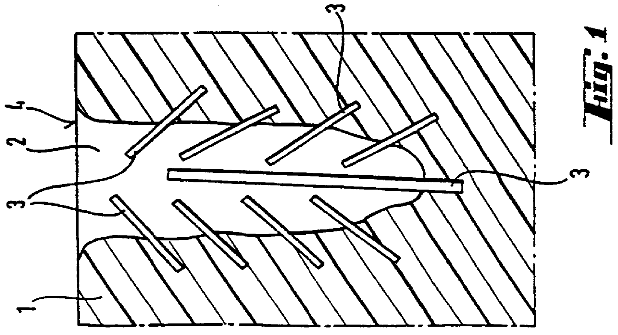
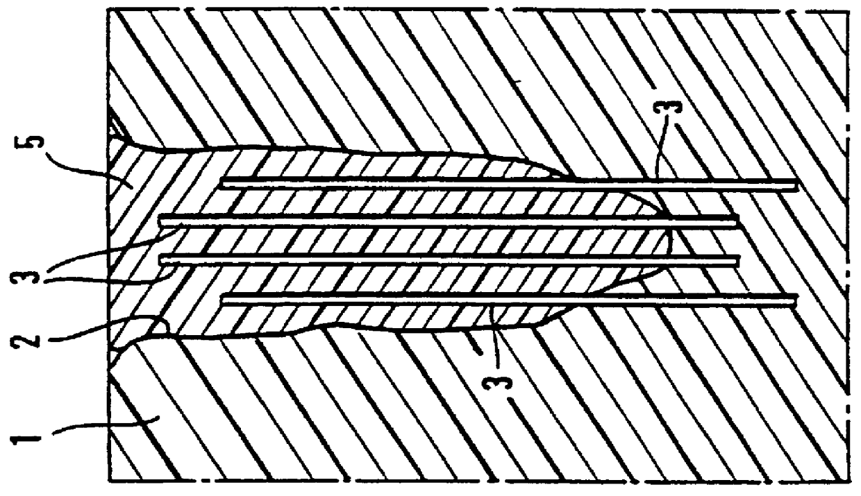
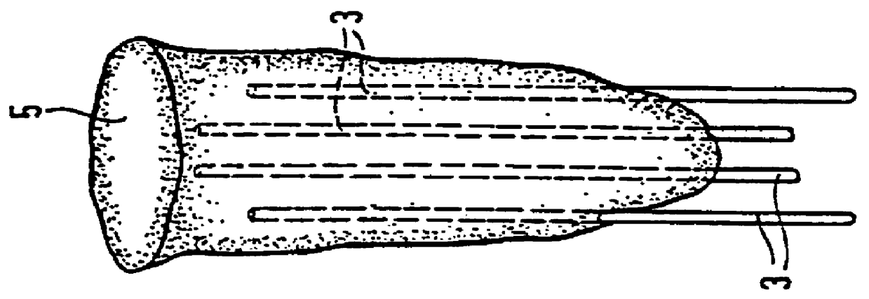
FIG. 5: FIG. 5 shows a lower jaw 10 in which a tumor 11 has formed. The bone part 12 stricken with the tumor 11 is removed from the lower jaw 10 and then an impression is made in the moulding material 1 (see the section according to FIG. 6). The mandrels 3 are placed in the cast cavity 2 so their ends project out of the moulding material 1. The arrangement of the mandrels 3 shown in FIG. 6 is reproduced as an example and can vary. After inserting the mandrels 3, the cast cavity 2 is filled with the biodegradable material that hardens into an implant 5.

FIG. 6: The bone part 12 removed from the lower jaw 10 according to the drawing in FIG. 6 is pressed into the moulding material 1 and rotated by 180.degree. compared to the drawing in FIG. 5 so that the upper, rounded section of the bone part 12, in accordance with the drawing in FIG. 6, is located at the bot...

example 3

With the use of FIGS. 9-18 another working example of the invention is described.

FIG. 9: FIG. 9 shows a sectional view of an implant core that also serves as a fixture. The term fixture designates the enossal part (inside the jaw bone) of an implant, which takes up the part of an implant construction (the visible part of the implant) projecting from the jaw bone. Such an implant core consists of an alloplastic, osseo-integratable material, e.g., titanium, Frialit, etc. It has the form of an elongated hollow body 18 with an inner space 15. Its outer side is structured, for example, in the form of a screw thread 16. Other designs also provide for a structuring of the inner side. An inside screw thread 17 is designed at the upper end of the inner space 15. In the wall of the hollow body 18 hollow spaces 19 that run parallel to the inner space 15 exist and are open at the top and closed at the bottom--i.e., at the end far away from the inside screw thread 17. Another arrangement of the ...

example 4

Another design is described below with reference to FIGS. 19-24.

FIG. 19: The hollow body 18, which consists of an osseo-integratable material, has an inner space 15 in the middle. Along the structured outer wall run elongated hollow spaces 19 corresponding to the working example described above. The hollow spaces 19 cross the grooves of the structured outer wall so that perforations 20 are formed that create a connection between the hollow spaces 19 and the outer surfaces of the hollow body 18. On the inner wall of the inner space 15 additional openings or perforations 29 to the outer surfaces are designed, whereby such openings 29 also exist in other working examples. The hollow body 18, which later serves as a fixture, has a screw thread 30 at the top, into which a temporary screw cover 31 can be screwed, whereby the screw thread 30 later serves as a means of affixing the tooth construction.

A rod-shaped mandrel 24 A with a handhold that ends in a handle 32, is stuck in the inner s...


PUM


Abstract

PCT No. PCT / EP96 / 05506 Sec. 371 Date Aug. 12, 1998 Sec. 102(e) Date Aug. 12, 1998 PCT Filed Dec. 10, 1996 PCT Pub. No. WO97 / 22308 PCT Pub. Date Jun. 26, 1997The invention relates to a medical implant, in particular a dental implant, intended for implantation in available cavities. Dental implants are implanted in extraction sockets. The implant is provided with reservoirs for a biologically active substance. An advantage of the implant is that, for dental procedures, it can be manufactured and implanted as part of a single therapeutic treatment. However, the implant can also be used as a release system for biologically active substances.

Description

This application was filed as international patent application PCT / EP96 / 05506 on Dec. 10, 1996.INTRODUCTION AND BACKGROUNDThe present invention concerns a medical implant that is intended to be inserted into a space with a prespecified dimension and to be filled and a process for producing the medical implant.It is known that in cases of extraction wounds bones change in such a way that the space that exists due to the extraction wound can no longer be filled by an implant whose dimension and shape corresponds exactly to the extracted hard connective tissue after a certain time period.A loss of a tooth that arises through a trauma when the tooth is unfavorably fractured and the root fragments cannot be saved can be mentioned as an example. Consequently, one must extract the fractured tooth and its root fragments. As a replacement one has been using a bridge or removable prothesis for a long time. They have the disadvantage of involving the neighboring teeth during anchoring, and if ...

Claims


Application Information

Patent Timeline
Patent Type & Authority Patents(United States)
IPC IPC(8): A61C8/00A61C13/20A61F2/00A61F2/30A61F2/02
CPCA61C8/00A61C8/0006A61C8/0036A61C13/20A61F2220/0008A61F2/30749A61F2002/30677A61F2002/30957
Inventor SUHONEN, JOUKOSCHUG, JENS
Owner DR JOUKO SUHONEN
Why Eureka
Try Eureka