Clamp for railroad coupler head

a coupler head and clamping technology, applied in couplings, manufacturing tools, instruments, etc., can solve the problems of not all coupler heads include flag holes, pusher locomotives cannot be connected without, and the positioning of equipment within the coupler head is not ideal, so as to reduce the possibility, reduce the possibility, and reduce the cost

Inactive Publication Date: 2000-10-24
THE UNION SWITCH & SIGNAL
View PDF14 Cites 27 Cited by
  • Summary
  • Abstract
  • Description
  • Claims
  • Application Information

AI Technical Summary

Benefits of technology

An advantage of the present invention is that the railroad coupler clamp and attached end-of-train equipment may be momentarily and temporarily hung from within the core hole before the scissors-like finger members are tightened within the coring hole.
Another advantage of the present invention is that the simple design provides cost-effective manufacturing.
Another adva

Problems solved by technology

Positioning the equipment within the coupler head is not ideal since it can be damaged by accidental mating with a coupler of another car, a situation which is likely in an active yard.
Moreover, pusher locomotives cannot be connected without first removing the equipment.
This arrangement avoids accidental equipment damage; however, the arrangement has the disadvantage that not all coupler

Method used


Image

  • Clamp for railroad coupler head
  • Clamp for railroad coupler head
  • Clamp for railroad coupler head

Examples


Embodiment Construction

of the Figures

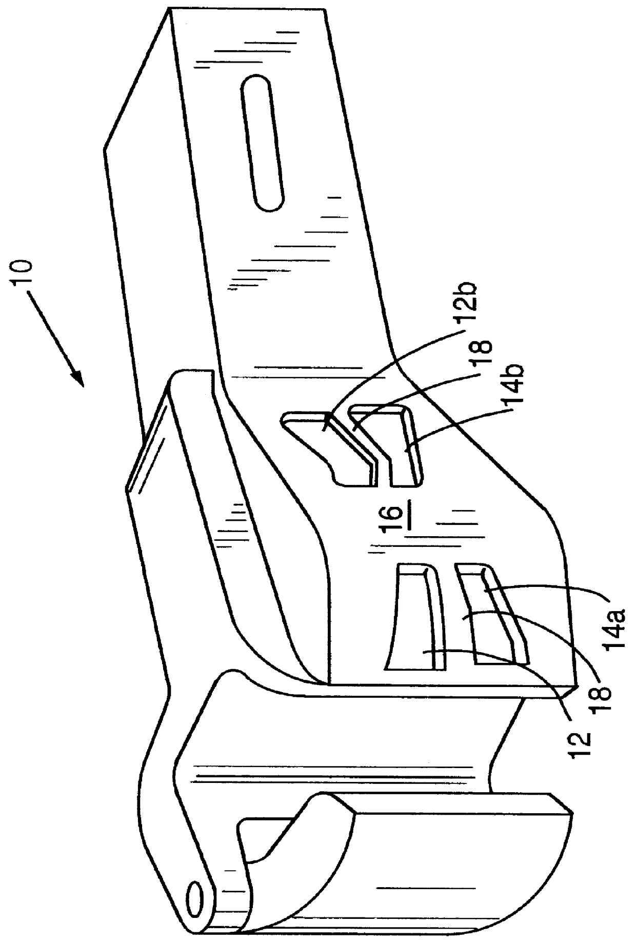
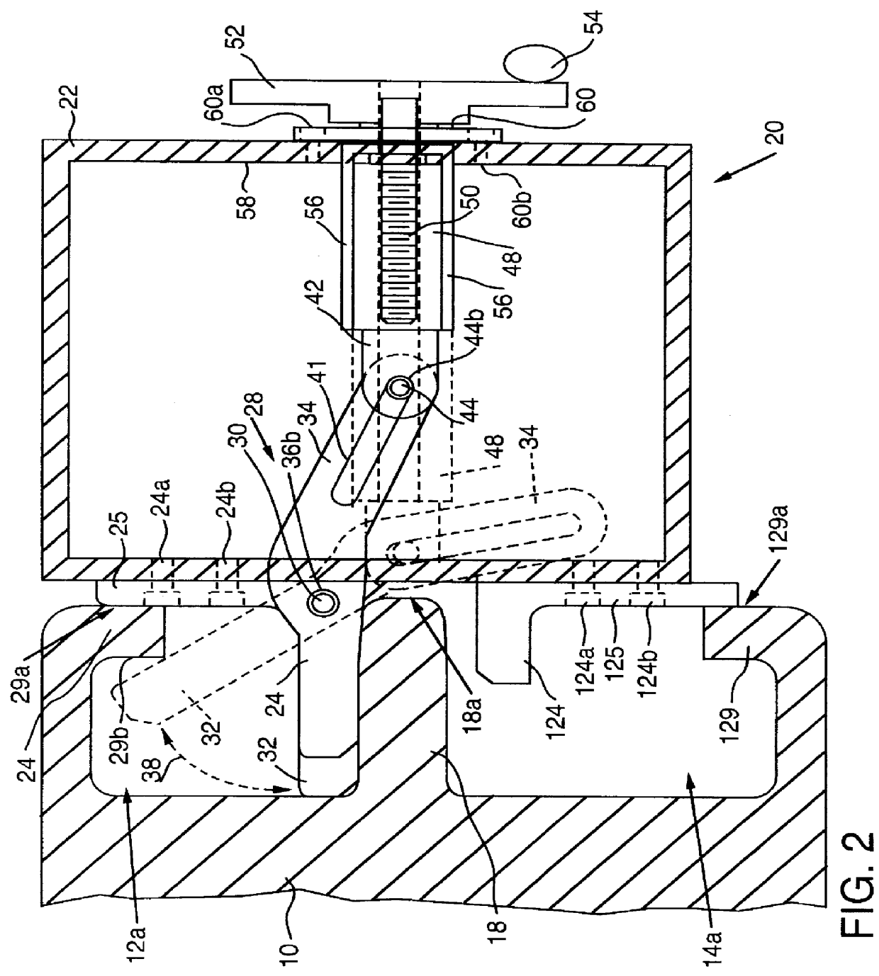
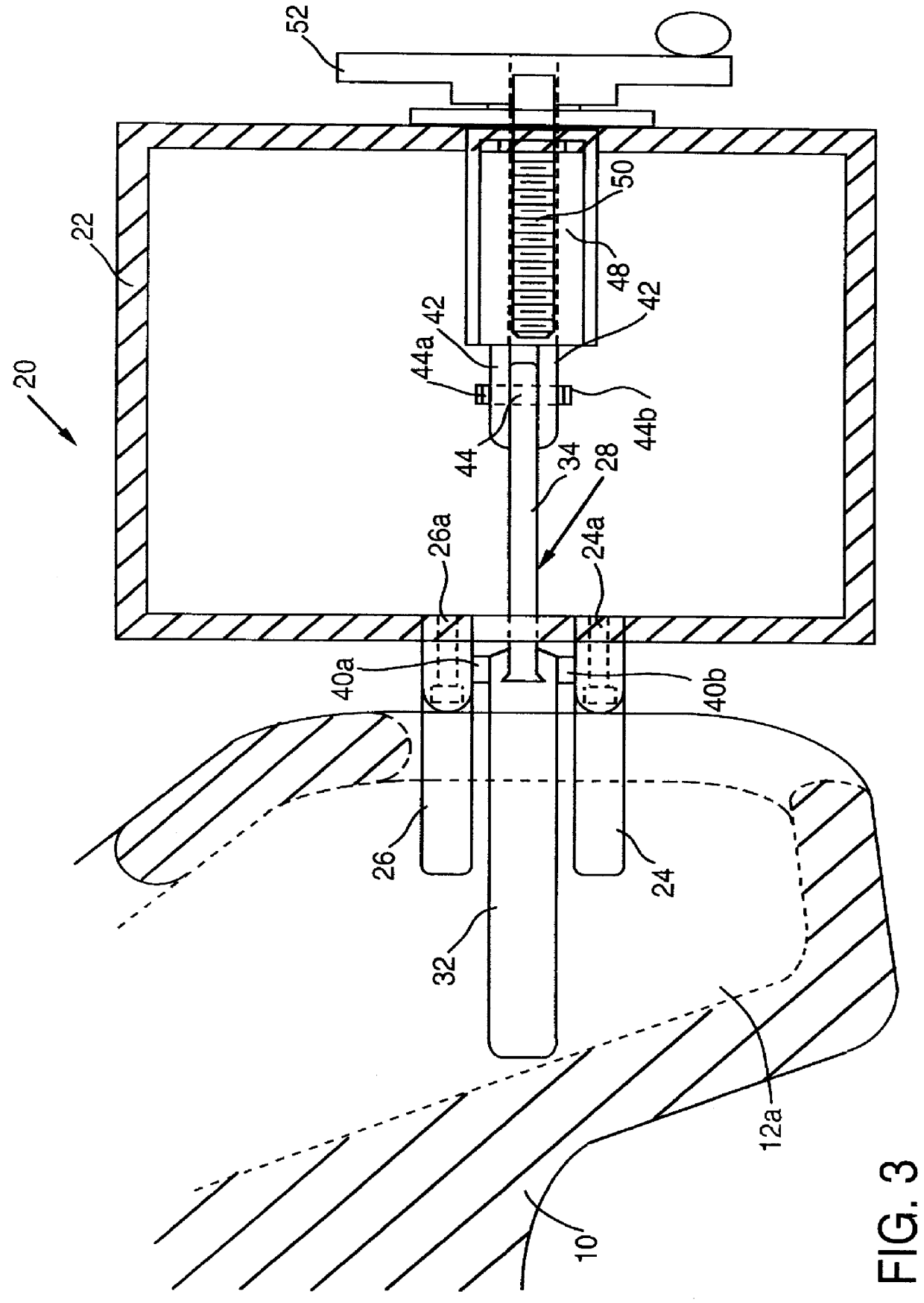
Referring now to the drawings, and more particularly to the side, top, and front views of FIGS. 2-5, a clamp 20 comprises a housing 22 on which finger members 24, 26 may fixedly be connected such that the finger members 24, 26 protrude substantially perpendicularly from the housing 22. Preferably, finger members 24 and 26 may be the same lengths, although finger members of different lengths may be used.

In a preferred embodiment, the finger members 24, 26 may extend from rails 25, 27 which extend upwardly along the housing 22, and through which screws 24a, 24b and 26a, 26b may pass, respectively, thereby to connect the finger members 24, 26 to the housing 22. These screws may be countersunk as shown. The rails 25, 27 may have sufficient length to contact and press against an outside surface 29a of an upper lip 29 of the uppermost core hole 12a (see FIG. 2), thereby providing stability of the clamp 20 when tightened against the coupler head 10. Similar rails 125, 127 may...


PUM


Abstract

A clamp for securing apparatus such as end-of-train equipment to a railroad coupler head includes a first finger member that is mounted to pivot about a pivot pin in scissors-like manner between a fixed second and third finger member affixed to a housing, a threaded rod and cooperating piston for pivoting the first finger member away from the fixed second and third finger members, a rail member for abutting against an outside surface of the coupler head, and a crank and handle for tightening the grip of the first, second and third fingers on the inner surfaces of the core hole when the crank is rotated. The pivoting of the first finger member is accomplished by driving a pin through a slotted clevis defined in a first end of the first finger member, such that the pin moves within the slot defined by the clevis when the pin is driven in one lateral direction generally toward the fixed second and third finger members, thereby urging the clevis downward about the pivot pin and urging the opposing second end of the first finger member to move upwardly away from the fixed second and third finger members. In a preferred embodiment, end-of-train signaling and monitoring equipment is connected to the clamp for the railroad coupler head.

Description

1. Field of the InventionThe present invention is generally related to a clamp which secures apparatus, such as an end-of-train marker light and telemetry equipment, to the coupler head of the last car in a train and, more particularly, to a railroad coupler clamp which secures equipment to the guard arm side of a coupler head.2. Description of the Related ArtAs is well known in the art, apparatus such as end-of-train signaling equipment is commonly used to meet modern railroad operating and safety requirements. Various train operating parameters (e.g., brakeline pressure, and the like) are remotely monitored by the end of train equipment, and telemetered to an engineer in the locomotive cab. In addition, the end-of-train equipment can include a marker light to identify the end of the train.Over the years, several railroad coupler mount configurations have been devised for securing the end-of-train signaling and monitoring equipment to the coupler head of the last car in a train. U....

Claims


Application Information

Patent Timeline
IPC IPC(8): B61G7/00
CPCB61G7/00Y10T403/7105Y10T403/591Y10T403/32073
Inventor ALFIERI, RICHARD P.DISK, DANIEL R.SMITH, DETLEV F.RAMSEY, ROGER H.
Owner THE UNION SWITCH & SIGNAL
Why Eureka
Try Eureka