Apparatus and method for grinding particulate material

a technology of particulate material and apparatus, which is applied in the direction of gas current separation, solid separation, grain milling, etc., can solve the problems of reducing the overall efficiency of the grinding chamber, and general wear of the targ

Inactive Publication Date: 2000-10-31
XEROX CORP
View PDF3 Cites 17 Cited by
  • Summary
  • Abstract
  • Description
  • Claims
  • Application Information

AI Technical Summary

Benefits of technology

This invention additionally provides grinding systems and methods that minimize target wear-related efficiency losses.
Various exemplary embodiments of the systems and methods according to this invention ensure particle-to-particle collisions and enhance the concentration of particles within the stream by ensuring that the particles are forced into the center of the fluid stream. This increases the number of particle-to-particle collisions and improves the efficiency of the grinding chamber.
In various exemplary embodiments of the systems and methods according to this invention, the fluid flow guide and the guide member co-operate to modify the flow of fluid around the fluid stream such that particulate material is forced into the center of the fluid stream. As a result, the particle concentration and the number of particle-to-particle collisions increases. This improves the grinding chamber efficiency.
In various exemplary embodiments of the systems and methods according to this invention, the apparatus further comprises at least two additional guide members. Each additional guide member can be mounted to the nozzle of an associated fluid source and extending substantially perpendicularly to the source axis. This provides a second region in which a flow of fluid toward the fluid stream is created. This further enhances the efficiency of these exemplary embodiments of the grinding apparatus and methods according to this invention.

Problems solved by technology

While this causes the particles to fragment, resulting in smaller particles, there is generally heavy wear of the target.
This in turn causes the target to become less efficient, causing a reduction in the overall efficiency of the grinding chamber.
A fluidized bed jet mill grinder is expensive to operate due to the large amount of energy required to produce sufficient compressed fluid to power the fluid jets.
That is, as the target wears during grinding, the grinding efficiency can drop significantly.
As a result, particles within the fluid streams collide, causing fragmentation and grinding of the particles.

Method used


Image

  • Apparatus and method for grinding particulate material
  • Apparatus and method for grinding particulate material
  • Apparatus and method for grinding particulate material

Examples


Embodiment Construction

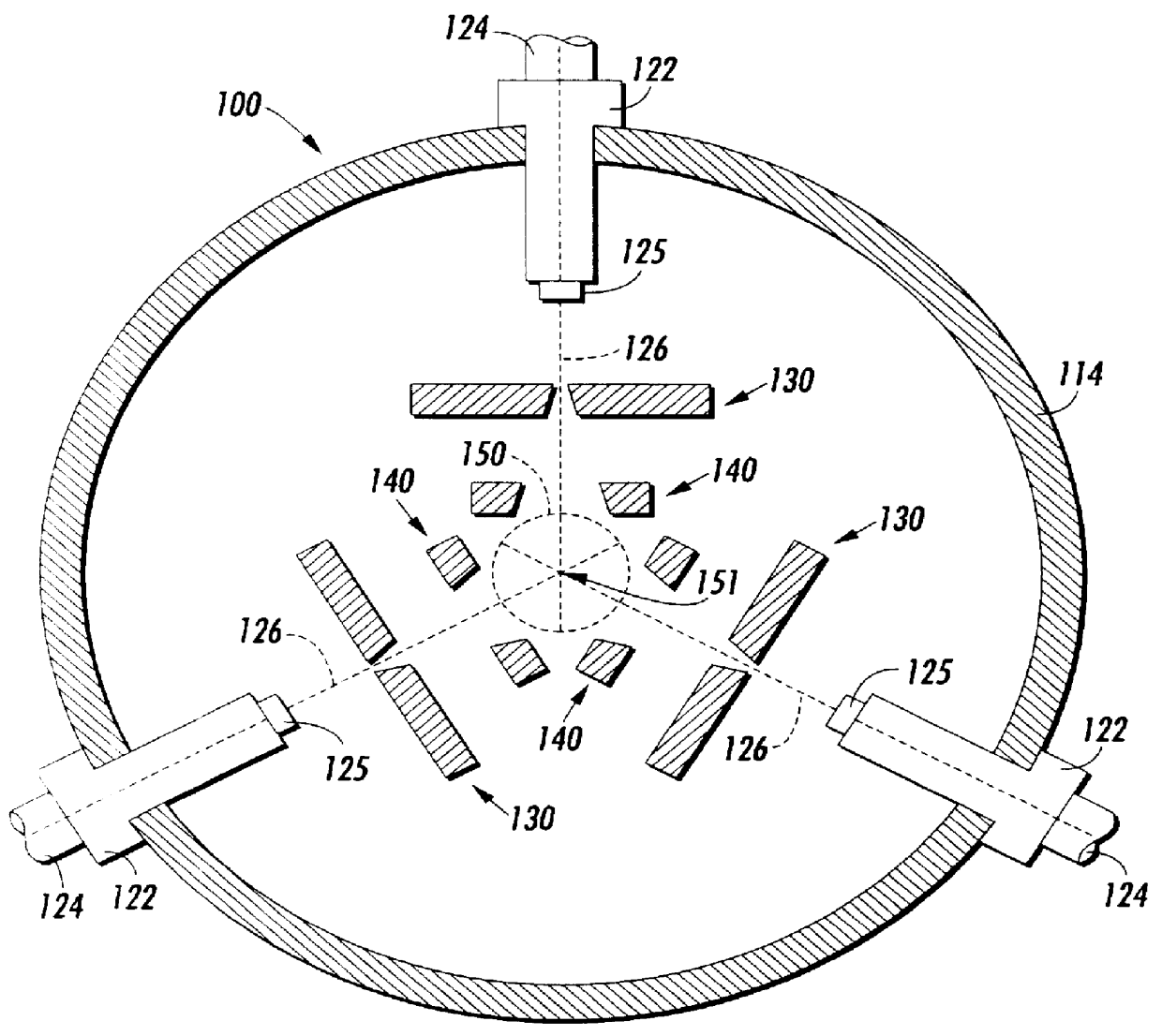
FIG. 1 shows a schematic representation of a cross-section through a grinding chamber 100 of a fluidized bed jet mill according to a first exemplary embodiment of the grinding apparatus and methods according to this invention. The grinding chamber 100 has a peripheral wall 114 that is generally cylindrical in shape and that defines a central axis 151 and an empty zone or region 150 surrounding the central axis 151 in the center of the grinding chamber 100.

Three fluid sources 122 are mounted on the peripheral wall 114. A nozzle 125 is mounted at the end of each fluid source 122 that is nearest the empty zone 150. Each fluid source 122 has an inlet 124 that connects that fluid source 122 to a supply of pressurized fluid. Each inlet 124 is positioned at the end of the corresponding fluid source 122 that is outside the grinding chamber 100. In various embodiments, the fluid sources 122 are mounted symmetrically around the central axis 151, as shown in FIG. 1. However, in other embodimen...


PUM


Abstract

An apparatus for grinding particulate material includes a grinding chamber. Fluid sources mounted on the peripheral wall of the grinding chamber generate a stream of fluid directed along the source axis of the fluid source towards the inside of the grinding chamber. Fluid flow guides associated with fluid sources have a first aperture. Guide members associated with fluid sources have a second aperture. Each guide member co-operates with the fluid stream of the associated fluid source and the associated fluid flow guide to draw fluid towards an upstream portion of the fluid stream and to direct fluid away from a downstream portion of the fluid stream. The fluid streams from the fluid sources overlap in an empty zone of the grinding chamber. The particulate material is introduced into the fluid streams, accelerated by the fluid streams and directed towards the empty zone. Thus particles from different streams collide in the empty zone.

Description

1. Field of the InventionThis invention relates to an apparatus and a method for grinding particulate material such as toner or the like.2. Related ArtParticulate material such as toner is generally ground in a fluidized bed jet mill grinder. A fluidized bed jet mill grinder operates by accelerating the particles in the particulate material using jets of air. The particles then impact either on a surface, or other particles, causing them to fragment. By providing fluidized bed jet mill grinder in an enclosed chamber, the particles undergo repeated impact until they are substantially reduced in size. This ground material may then be removed from the grinding chamber.U.S. Pat. No. 5,133,504 places an impact target at the center of the grinding chamber. The target is configured such that the particles are accelerated toward the target by one of several jets of air, causing the particles to impact on the target surface. While this causes the particles to fragment, resulting in smaller p...

Claims


Application Information

Patent Timeline
Patent Type & Authority Patents(United States)
IPC IPC(8): B02C19/06
CPCB02C19/065
Inventor GEURTS, FRANK L. S.O'LOUGHLIN, DAWN M.
Owner XEROX CORP
Why Eureka
Try Eureka